Maintaining your 2005 Ford E-350 van requires understanding its electrical system, and a key component of that is the fuse box. Fuses protect your vehicle’s circuits from overloads, preventing damage to sensitive components. Knowing the location and function of each fuse is essential for troubleshooting electrical issues. This guide provides detailed fuse box diagrams for your 2005 Ford E-350, along with information to help you understand how it relates to your vehicle’s OBD2 port, which is crucial for diagnostics.
Passenger Compartment Fuse Box Diagram
The passenger compartment fuse panel in your 2005 Ford E-350 is located under the dashboard, typically on the driver’s side. This fuse box houses fuses for many of the interior electrical systems.
| Type | No. | Description |
|---|---|---|
| Fuse MINI 5A | 1 | 4-Wheel Anti-lock Brake System (4WABS) module |
| Fuse MINI 10A | 2 | Remote Keyless Entry (RKE), O/D cancel |
| Fuse MINI 15A | 3 | Trip computer, Radio, Video Cassette Player (VCP) and video screens, Overhead console |
| Fuse MINI 15A | 4 | Courtesy lamps |
| Fuse MINI 30A | 5 | Power lock switches, Power locks without RKE |
| Fuse MINI 10A | 6 | Brake-shift interlock, Daytime Running Lamps (DRL) module |
| Fuse MINI 10A | 7 | Multi-function switch, Turn signals |
| Fuse MINI 30A | 8 | Radio capacitor(s) Ignition coil, Powertrain Control Module (PCM) diode, PCM power relay |
| Fuse MINI 5A | 9 | Wiper control module |
| Fuse MINI 20A | 10 | Main light switch, Park lamps, License lamp (external lamps), Multi-function switch (flash-to-pass) |
| Fuse MINI 15A | 11 | Multi-function switch (hazards), Brake lamp switch, Brake lamps |
| Fuse MINI 15A | 12 | Back-up lamps, Auxiliary battery relay [gasoline engine only], Trailer tow relay |
| Fuse MINI 15A | 13 | Blend door actuator, Function selector switch |
| Fuse MINI 5A | 14 | Instrument cluster |
| Fuse MINI 5A | 15 | Trailer battery charge relay, Cluster |
| Fuse MINI 30A | 16 | Power seats |
| Fuse MINI 5A | 17 | Power mirrors |
| Fuse MINI 10A | 20 | Restraints |
| Fuse MINI 15A | 22 | Memory power radio, Rear seat video control unit, Battery saver relay, Instrument cluster, Courtesy lamp relay, Accessory delay relay |
| Fuse MINI 20A | 23 | Power locks w/RKE |
| Fuse MINI 10A | 25 | Left headlamp (low beam) |
| Fuse MINI 20A | 26 | Cigar lighter, Diagnostics |
| Fuse MINI 5A | 27 | Radio |
| Fuse MINI 15A | 30 | Headlamps (high beam indicator) |
| Fuse MINI 10A | 31 | Right headlamp (low beam) |
| Fuse MINI 20A | 32 | Power point #1 (instrument panel) |
| Fuse MINI 10A | 33 | Start relay |
| Fuse MINI 5A | 36 | Instrument illumination |
| Fuse MINI 10A | 39 | Trailer tow electric brake, Center High-Mounted Stop Lamp (CHMSL), Brake lamps |
| Fuse MINI 20A | 40 | Power point #2 (2nd row seating position – driver side) |
| Fuse MINI 30A | 41 | Modified vehicle |
| Circuit breaker ATO | 42 | Power windows |
| Circuit breaker ATO | 44 | Wiper/washer |
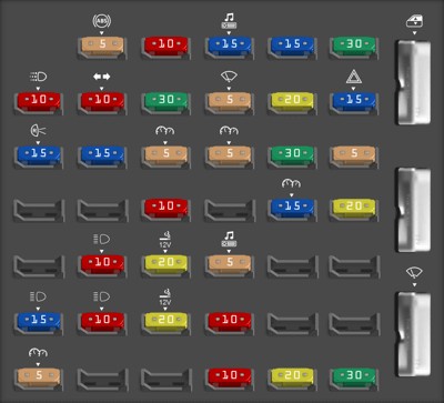


This diagram illustrates the layout and numbering of the fuses in the passenger compartment fuse box of a 2005 Ford E350, aiding in quick fuse identification for electrical repairs.
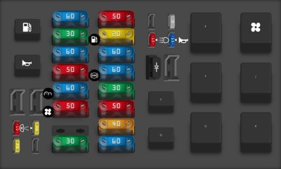
Power Distribution Box Diagram
Located in the engine compartment, the power distribution box contains high-current fuses and relays that manage the Ford E-350’s primary electrical functions.
| Type | No. | Description |
|---|---|---|
| Diode ATO | 1 | Powertrain Control Module (PCM) diode |
| Fuse MINI 10A | 3 | Daytime Running Lamps (DRL) module, A/C clutch |
| Fuse MINI 15A | 5 | Horn relay |
| Fuse MINI 2A | 6 | Brake pressure switch |
| Fuse MAXI 60A | 7 | Ignition switch, Fuse panel, Accessory delay |
| Fuse MAXI 40A | 8 | Trailer battery charge relay |
| Fuse MAXI 50A | 9 | Modified vehicle power |
| Fuse MAXI 30A | 10 | Electric brake controller |
| Fuse MAXI 60A | 11 | 4-Wheel Anti-lock Brake System (4WABS) |
| Fuse MAXI 60A | 12 | I/P fuses 29, 34, 35, 40 and 41 |
| Fuse MAXI 20A | 13 | Fuel pump relay |
| Fuse MAXI 50A | 14 | Auxiliary blower relay |
| Fuse MAXI 30A | 15 | Main light switch |
| Fuse MAXI 50A | 17 | Blower motor relay (blower motor) |
| Fuse MAXI 60A | 18 | Engine compartment fuses 3, 5, 23 and 26, Instrument panel fuses 26 and 32, Start relay |
| Fuse MAXI 50A | 19 | IDM relay [Diesel engine only] |
| Fuse MAXI 60A | 20 | Auxiliary battery relay [gasoline engine only], PDB fuses 8 and 24 |
| Fuse MAXI 30A | 21 | PCM power relay, PDB fuse 27 |
| Fuse MAXI 60A | 22 | I/P fuses 4, 5, 10, 11, 16, 17, 22 and 23, Circuit breaker 44 |
| Fuse MINI 20A | 24 | Trailer tow running lamps and back-up lamp relays |
| Fuse MINI 20A | 26 | Trailer tow turn signals |
| Fuse MINI 10A | 27 | PCM |
| Relay | A | Fuel pump relay |
| Relay | B | Horn relay |
| Relay | C | Trailer back-up lamps relay |
| Relay | D | Trailer running lamps relay |
| Relay | E | Trailer battery charge relay |
| Relay | F | IDM relay [Diesel only] |
| Relay | G | PCM relay |
| Relay | H | Blower motor relay |
| Relay | J | Accessory delay relay |
| Relay | K | Start relay |
This image presents the power distribution box fuse layout for the 2005 Ford E350, essential for diagnosing issues related to engine and main vehicle systems.
Instrument Panel Relay Module Diagram
The instrument panel relay module is another critical area for electrical relays in your 2005 Ford E-350, managing interior lighting and convenience features.
| Type | No. | Description |
|---|---|---|
| Relay | 1 | Interior lamps |
| Relay | 2 | Open |
| Relay | 3 | Open |
| Relay | 4 | Battery saver |
This diagram details the instrument panel relay module in a 2005 Ford E350, crucial for understanding circuits controlling interior lights and battery management.
Engine Compartment Relay Module Diagram
In addition to the power distribution box, an engine compartment relay module further organizes relays for engine-specific and trailer towing functions in the 2005 E-350.
| Type | No. | Description |
|---|---|---|
| Relay | 1 | PCM back-up lamp |
| Relay | 2 | A/C control |
| Relay | 3 | Trailer tow right turn |
| Relay | 4 | Trailer tow left turn |
This image shows the engine compartment relay module layout for a 2005 Ford E350, important for diagnosing relay-related issues in the engine and towing systems.
Fuses and Your 2005 Ford E-350 OBD2 Port
While “05 Ford E350 Fuse Obd2” might suggest a specific fuse directly labeled “OBD2,” it’s more accurate to understand that several fuses can indirectly affect the functionality of your OBD2 port. The OBD2 port, or On-Board Diagnostics II port, is used to connect diagnostic scanners to your vehicle’s computer system. This system helps read trouble codes and diagnose problems.
Fuse #26 (20A) in the passenger compartment fuse panel is labeled “Cigar lighter, Diagnostics.” This fuse is very likely to power your OBD2 port. If you are experiencing issues connecting your scanner or are not getting power to your OBD2 port, this is the first fuse to check. A blown fuse #26 can prevent your diagnostic scanner from communicating with your 2005 Ford E-350’s computer.
Furthermore, other fuses related to the Powertrain Control Module (PCM) and engine sensors can also impact the data available through the OBD2 port. For instance, fuses related to the PCM power relay or sensor circuits could indirectly prevent accurate readings or communication via the OBD2 port. Always consult your fuse diagrams to understand which fuses are linked to critical engine and diagnostic systems.
Troubleshooting your 2005 Ford E-350 electrical issues and diagnostic port problems should always start with checking the relevant fuses. By using these diagrams and understanding the fuse functions, you can effectively maintain your vehicle and ensure your OBD2 port is ready for diagnostic checks when needed. Remember to always replace a blown fuse with one of the same amperage to avoid further electrical problems.