Understanding the fuse box in your 2004 Ford F-150 is crucial for diagnosing and resolving electrical issues. Fuses protect your vehicle’s electrical circuits from overloads, and knowing their location and function can save you time and money on repairs. While the term “OBD2 fuse” might lead you to a specific fuse labeled as such, it’s more accurate to think about the fuse that powers your OBD2 diagnostic port. This port is essential for connecting scan tools to read vehicle data and diagnose problems. Let’s explore the fuse box locations and identify the relevant fuses for your 2004 Ford F-150, ensuring you can keep your truck running smoothly.
Decoding the Fuse Boxes in Your 2004 Ford F-150
The 2004 Ford F-150 is equipped with not just one, but three distinct fuse boxes, each serving different electrical systems. These are strategically placed throughout the vehicle for optimal access and circuit protection. Familiarizing yourself with each location is the first step in effective electrical troubleshooting.
- Passenger Compartment Fuse Panel: This is likely the most frequently accessed fuse box, located inside the vehicle. It houses fuses for many of the interior and convenience features.
- Auxiliary Relay Box (with DRL): If your F-150 is equipped with Daytime Running Lights (DRL), you’ll find this auxiliary box, which manages additional relays and fuses related to specific lighting and control systems.
- Auxiliary Relay Box (without DRL): For models without Daytime Running Lights, there’s a slightly different auxiliary relay box configuration, still managing important relays and fuses.
Let’s delve into each fuse box with diagrams and detailed fuse listings to pinpoint the circuits and potentially the fuse related to your OBD2 port.
Passenger Compartment Fuse Panel Diagram and Fuse List
The passenger compartment fuse panel, often the primary fuse box owners will interact with, is responsible for a wide array of systems within your 2004 Ford F-150. This includes everything from interior lights and wipers to critical engine management and safety systems.
Here’s a breakdown of the fuses located in the passenger compartment fuse panel:
| Type | No. | Description |
|---|---|---|
| Fuse MINI 10A | 1 | Run/Accessory – Wipers, Instrument cluster |
| Fuse MINI 20A | 2 | Stop/Turn lamps, Speed control deactivate switch |
| Fuse MINI 5A | 3 | Power mirrors, Memory logic power, Memory seats and pedals |
| Fuse MINI 10A | 4 | DVD battery power |
| Fuse MINI 5A | 5 | Keep alive memory for Powertrain Control Module (PCM) and climate control module |
| Fuse MINI 15A | 6 | Parklamps, BSM, Instrument panel illumination |
| Fuse MINI 5A | 7 | Radio (start signal) |
| Fuse MINI 10A | 8 | Heated mirrors, Switch indicator |
| Fuse MINI 20A | 10 | Trailer tow back-up lamps relay (PCB1), Trailer tow parklamp relay (R201) |
| Fuse MINI 10A | 11 | A/C clutch, 4×4 solenoid |
| Fuse MINI 10A | 13 | Climate control module power |
| Fuse MINI 10A | 14 | Back-up lamp and Daytime Running Lamps (DRL) relay coil, A/C pressure switch, Brake-shift interlock solenoid |
| Fuse MINI 5A | 15 | Overdrive cancel, Cluster, Brake-Shift Interlock (BSI) |
| Fuse MINI 10A | 16 | ABS module (Run/Start power) |
| Fuse MINI 15A | 17 | Fog lamp relay (R202) |
| Fuse MINI 10A | 18 | Run/Start feed – Flasher relay, Electrochromatic mirror, Heated seats, BSM, Compass, RSS (Reverse Sensing System) |
| Fuse MINI 10A | 19 | Restraints (Air bag module) |
| Fuse MINI 15A | 20 | PCM 4×4 power |
| Fuse MINI 15A | 21 | Cluster keep alive power |
| Fuse MINI 10A | 22 | Delayed accessory power for audio, power door lock switch and moonroof switch illumination |
| Fuse MINI 10A | 23 | RH low beam headlamp |
| Fuse MINI 15A | 24 | Battery saver power for demand lamps |
| Fuse MINI 10A | 25 | LH low beam headlamp |
| Fuse MINI 20A | 26 | Horn relay (PCB3), Horn power |
| Fuse MINI 5A | 27 | Passenger Air bag Deactivation (PAD) warning lamp, Cluster air bag warning lamp, Cluster RUN /START power |
| Fuse MINI 5A | 28 | SecuriLock transceiver (PATS) |
| Fuse MINI 15A | 29 | PCM 4×4 power |
| Fuse MINI 20A | 31 | Radio power |
| Fuse MINI 15A | 32 | Vapor Management Valve (VMV), A/C clutch relay, Canister vent, Heated Exhaust Gas Oxygen (HEGO) sensors #11 and #21, CMCV, Mass Air Flow (MAF) sensor, VCT |
| Fuse MINI 15A | 33 | Shift solenoid, CMS #12 and #22 |
| Fuse MINI 20A | 34 | Fuel injectors and PCM power |
| Fuse MINI 20A | 35 | Instrument cluster high beam indicator, High beam headlamps |
| Fuse MINI 10A | 36 | Trailer tow right turn/stop lamps |
| Fuse MINI 20A | 37 | Rear power point |
| Fuse MINI 25A | 38 | Subwoofer power |
| Fuse MINI 20A | 39 | Instrument panel power point |
| Fuse MINI 20A | 40 | Low beam headlamps, DRL |
| Fuse MINI 20A | 41 | Cigar lighter, Diagnostic connector power |
| Fuse MINI 10A | 42 | Trailer tow left turn/stop lamps |
| Fuse FMX/JCase 30A | 101 | Starter solenoid |
| Fuse FMX/JCase 20A | 102 | Ignition switch feed |
| Fuse FMX/JCase 20A | 103 | ABS valves |
| Fuse FMX/JCase 30A | 105 | Electric trailer brakes |
| Fuse FMX/JCase 30A | 106 | Trailer tow battery charge |
| Fuse FMX/JCase 30A | 107 | Power door locks (BSM) |
| Fuse FMX/JCase 30A | 108 | Passenger power seat |
| Fuse FMX/JCase 30A | 109 | Driver power seat, Adjustable pedals |
| Fuse FMX/JCase 30A | 111 | 4×4 relays |
| Fuse FMX/JCase 40A | 112 | ABS pump power |
| Fuse FMX/JCase 30A | 113 | Wipers and washer pump |
| Fuse FMX/JCase 40A | 114 | Heated backlite, Heated mirror power |
| Fuse FMX/JCase 30A | 116 | Blower motor |
| Fuse FMX/JCase 30A | 118 | Heated seats |
| Circuit breaker MAXI | 401 | Power windows, Moonroof, Power sliding backlite |
| Relay | R01 | Starter solenoid |
| Relay | R02 | Accessory delay |
| Relay | R03 | Hi-beam headlamps |
| Relay | R04 | Heated backlite |
| Relay | R05 | Trailer tow battery charge |
| Relay | R06 | Blower motor |
| Relay | R201 | Trailer tow park lamps |
| Relay | R202 | Fog lamps |
| Relay | R203 | PCM |
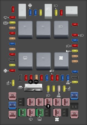
Finding the OBD2 Fuse: Looking at the list, Fuse #41 (20A) is labeled “Cigar lighter, Diagnostic connector power”. This is the fuse you’re most likely looking for when addressing OBD2 port issues. If your OBD2 scanner is not powering up when connected to your 2004 Ford F-150, this fuse should be your first point of inspection.
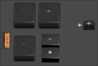
Auxiliary Relay Box (with DRL) Diagram and Fuse List
For 2004 Ford F-150 models equipped with Daytime Running Lights, the auxiliary relay box adds another layer of electrical management.
Here are the components within the Auxiliary Relay Box (with DRL):
| Type | No. | Description |
|---|---|---|
| Fuse ATO 5A | F01 | Clockspring illumination |
| Relay | R01 | 4×4 CCW |
| Relay | R02 | 4×4 CW |
| Relay | R03 | Daytime Running Lamps (DRL) [if equipped, otherwise not used] |
| Relay | R201 | DRL |
| Relay | R202 | A/C clutch |
| Diode ATO | D01 | A/C clutch diode |
This auxiliary box primarily manages relays and a few fuses related to lighting and the 4×4 system in DRL-equipped models. It is less likely to be directly related to the OBD2 port, but it’s important to know its location and function for comprehensive electrical system understanding.
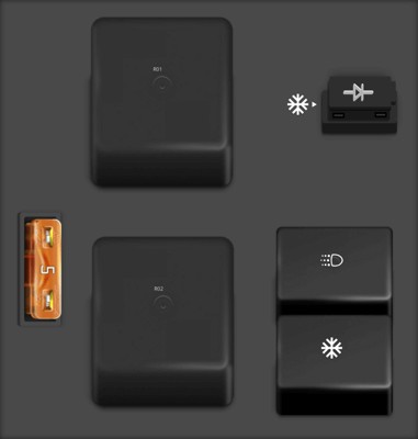
Auxiliary Relay Box (without DRL) Diagram and Fuse List
For 2004 Ford F-150 models without Daytime Running Lights, the auxiliary relay box configuration is slightly different, although its core function of managing relays remains similar.
The components for the Auxiliary Relay Box (without DRL) are as follows:
| Type | No. | Description |
|---|---|---|
| Fuse ATO 5A | F01 | Clockspring illumination |
| Relay | R01 | 4×4 CCW |
| Relay | R02 | 4×4 CW |
| Relay | R201 | DRL |
| Relay | R202 | A/C clutch |
| Diode ATO | D01 | A/C clutch diode |
Similar to the DRL version, this auxiliary box is more focused on relays and specific vehicle options. Again, for OBD2 port issues, the passenger compartment fuse box is the primary area to investigate.
Conclusion
Locating the correct fuse is a fundamental step in automotive electrical repair. For your 2004 Ford F-150, understanding the three fuse box locations and their respective diagrams is essential. Specifically, if you are experiencing issues with your OBD2 diagnostic port, focus on the passenger compartment fuse panel and check Fuse #41 (20A), which is designated for “Diagnostic connector power”. By utilizing these diagrams and fuse lists, you can effectively troubleshoot and maintain the electrical system of your 2004 Ford F-150. Remember to always consult your vehicle’s owner’s manual for the most accurate and up-to-date information regarding fuse locations and specifications.