Maintaining the electrical system of your 2005 Mercury Grand Marquis is crucial for its reliability and performance. Understanding the fuse box locations and the function of each fuse and relay is a fundamental step in diagnosing and resolving electrical issues. This guide provides a detailed overview of the fuse box diagrams for your 2005 Mercury Grand Marquis, alongside essential information about the OBD2 port, which is vital for modern vehicle diagnostics and often referenced in conjunction with wiring schematics for troubleshooting.
Fuse Box Locations on Your 2005 Mercury Grand Marquis
Your 2005 Mercury Grand Marquis is equipped with two primary fuse boxes. Knowing the location of each is the first step in addressing any electrical concerns. These are the Power Distribution Box and the Passenger Compartment Fuse Panel.
Power Distribution Box Diagram
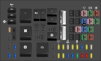
The power distribution box, often located in the engine compartment, houses fuses and relays that protect and control high-current circuits. Refer to the diagram and table below for the specifics of the power distribution box in your 2005 Mercury Grand Marquis.
| Type | No. | Description |
|---|---|---|
| Fuse MINI 20A | 1 | Ignition switch (Key in, RUN 1, RUN 2) |
| Fuse MINI 25A | 2 | Ignition switch (RUN/START, RUN/ACC, START) |
| Fuse MINI 10A | 3 | Powertrain Control Module (PCM) keep alive power |
| Fuse MINI 20A | 4 | Fuel relay feed |
| Fuse MINI 10A | 5 | Rear Air Suspensión Module (RASM), VASM |
| Fuse MINI 15A | 6 | Alternator regulator |
| Fuse MINI 30A | 7 | PCM relay feed |
| Fuse MINI 20A | 8 | Driver’s Door Module (DDM), Door locks |
| Fuse MINI 15A | 9 | Ignition coil relay feed |
| Fuse MINI 20A | 10 | Horn relay feed |
| Fuse MINI 15A | 11 | A/C clutch relay feed |
| Fuse MINI 25A | 12 | Audio |
| Fuse MINI 20A | 13 | Instrument panel power point |
| Fuse MINI 20A | 14 | Stop lamp switch |
| Fuse MINI 20A | 15 | Heated seats |
| Fuse MINI 20A | 16 | Daytime Running Lamps (DRL) module |
| Fuse MINI 15A | 19 | Injectors |
| Fuse MINI 15A | 20 | PCM, Mass Air Flow (MAF) sensor |
| Fuse MINI 15A | 21 | Powertrain loads and sensors |
| Fuse MINI 5A | 24 | Radio mute |
| Fuse FMX/JCase 40A | 101 | Blower relay feed |
| Fuse FMX/JCase 50A | 102 | Cooling fan |
| Fuse FMX/JCase 50A | 103 | Instrument panel (I/P) fuse box feed #1 (I/P fuses 23, 25, 27 and 31) |
| Fuse FMX/JCase 40A | 104 | Instrument panel (I/P) fuse box feed #2 (I/P fuses 1, 3, 5, 7 and 9) |
| Fuse FMX/JCase 30A | 105 | Starter relay feed |
| Fuse FMX/JCase 40A | 106 | Anti-lock Brake System (ABS) module (Pump) |
| Fuse FMX/JCase 40A | 107 | Rear defroster relay feed |
| Fuse FMX/JCase 20A | 108 | Moonroof |
| Fuse FMX/JCase 20A | 109 | ABS module (Valves) |
| Fuse FMX/JCase 30A | 110 | Wiper module |
| Fuse FMX/JCase 30A | 112 | Air suspensión compressor |
| Relay | 201 | A/C clutch |
| Relay | 203 | Ignition coil |
| Relay | 204 | PCM |
| Relay | 206 | Fuel |
| Relay | 209 | Horn |
| Relay | 301 | Starter |
| Relay | 302 | Air compressor |
| Relay | 303 | Blower |
| Relay | 304 | Power windows relay (RUN/ACC) |
| Diode ATO | 501 | A/C clutch |
| Diode ATO | 502 | PCM |
| Diode ATO | 503 | Horn, Door latch |
| Circuit breaker MAXI | 601 | Power seats, Lumbar, Decklid |
| Circuit breaker MAXI | 602 | Power windows relay feed (RUN/ACC) |
Passenger Compartment Fuse Panel Diagram
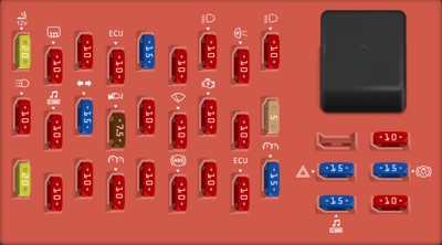
The passenger compartment fuse panel, usually located inside the car, often under the dashboard or side panel, protects circuits for interior components and accessories. The following diagram and table detail the passenger compartment fuse panel for your 2005 Mercury Grand Marquis.
| Type | No. | Description |
|---|---|---|
| Fuse MINI 15A | 1 | Cluster, Lighting Control Module (Interior Lighting) |
| Fuse MINI 10A | 2 | Ignition (ON) – Electronic Automatic Temperature Control (EATC) module, A/C mode switch [vehicles equipped with EATC] |
| Fuse MINI 10A | 3 | EATC module |
| Fuse MINI 10A | 4 | Ignition (ON) – Anti-lock Brake System (ABS) module, Positive Crankcase Ventilation (PCV) |
| Fuse MINI 10A | 5 | Speed control deactivation switch, Stop signal, Brake-Transmission Shift Interlock (BTSI) (column-shift transmission) |
| Fuse MINI 10A | 6 | Ignition (ON) – Cluster |
| Fuse MINI 10A | 7 | LCM (Park lamps, Switch illumination) |
| Fuse MINI 10A | 8 | Ignition (ON) – Rear Air Suspensión Module (RASM), Variable Assist Power Steering (VAPS) |
| Fuse MINI 20A | 9 | LCM (Headlamps, Cornering lamps) |
| Fuse MINI 5A | 10 | Ignition (ON/START) – Driver’s Door Module (DDM) |
| Fuse MINI 10A | 11 | Ignition (START) – ON/ACC relay coil |
| Fuse MINI 10A | 12 | Ignition (ON/START) – Starter relay coil |
| Fuse MINI 10A | 13 | Ignition (START) – Wiper module |
| Fuse MINI 10A | 14 | Ignition (ON) – BTSI (Floor-shift transmission) |
| Fuse MINI 7.5A | 15 | Ignition (START) – LCM, Door lock switch illumination, Heated seat switch illumination, Moonroof, Overhead console, Electrochromatic mirror |
| Fuse MINI 15A | 16 | Ignition (ON) – Turn signals |
| Fuse MINI 10A | 17 | Ignition (START) – Audio |
| Fuse MINI 10A | 18 | Ignition (ON) – A/C mode switch (vehicles equipped with manual A/C), Blend door, DDM, Heated seat modules, Daytime Running Lamps (DRL) module |
| Fuse MINI 10A | 19 | Left-hand low beam, DRL |
| Fuse MINI 10A | 20 | Ignition (ON/ACC) – Back-up lamps |
| Fuse MINI 10A | 21 | Right-hand low beam, DRL |
| Fuse MINI 10A | 22 | Ignition (ON/ACC) – Restraint Control Module (RCM), Occupant Classification Sensor (OCS), Passenger Air bag Deactivation Indicator (PADI) |
| Fuse MINI 15A | 23 | Multi-function switch (Flash-to-pass) |
| Fuse MINI 10A | 24 | Ignition (ON/ACC) – Passive Anti-Theft System (PATS) module, Powertrain Control Module (PCM) relay coil, Fuel relay coil, Ignition coil relay coil |
| Fuse MINI 10A | 25 | Autolamp/Sunload sensor, Power mirrors, Door lock switches (DDM), Adjustable pedal switch |
| Fuse MINI 10A | 26 | Ignition (ON/ACC) – Analog cluster, Warning lamp module, LCM, Overdrive cancel switch, Rear defroster relay coil |
| Fuse MINI 20A | 27 | Cigar lighter, OBD II, Power point |
| Fuse MINI 10A | 28 | Center High-Mounted Stop Lamp (CHMSL) |
| Fuse MINI 15A | 29 | Audio |
| Fuse MINI 15A | 30 | Stop lamps, MFS |
| Fuse MINI 15A | 31 | Hazards |
| Fuse MINI 10A | 32 | Mirror heaters, Rear defroster switch indicator |
Understanding the OBD2 Port and Wiring Schematics
The On-Board Diagnostics II (OBD2) port in your 2005 Mercury Grand Marquis is typically located under the dashboard on the driver’s side. This port is essential for connecting diagnostic scanners to read vehicle data, including trouble codes that can indicate electrical or mechanical issues.
While this article primarily focuses on fuse box diagrams, it’s important to understand how they relate to the broader electrical system and wiring schematics. Fuses are protective devices in the wiring circuits. When diagnosing electrical problems, especially those identified through OBD2 codes, understanding the fuse box layout is often the first step. A wiring schematic provides a comprehensive map of the electrical circuits, showing how fuses, relays, and components are interconnected.
For in-depth electrical troubleshooting, particularly when dealing with complex issues or interpreting OBD2 diagnostic information, a complete 2005 Mercury Grand Marquis wiring schematic is invaluable. These schematics provide detailed circuit diagrams that can help pinpoint the exact location of faults within the system.
Note: While we aim to provide helpful information, always consult a professional mechanic for complex electrical repairs. Incorrectly diagnosing or repairing electrical issues can lead to further damage or safety risks.
This guide should assist you in understanding the fuse box layout of your 2005 Mercury Grand Marquis and its relationship to the OBD2 system and wiring in general. Always refer to your vehicle’s repair manual for the most accurate and detailed information.