For car enthusiasts and DIY electronics hobbyists, accessing vehicle diagnostic data can unlock a world of possibilities. A basic OBD2 scanner, often referred to as a “Basx Obd2 Scanner” in online communities, is an inexpensive tool to tap into this data. By making a few simple modifications, you can interface these scanners directly with an Arduino for custom projects like creating your own dashboards, logging data, or even automating car functions. This guide will walk you through the process of modifying an ELM327-based OBD2 scanner for seamless communication with your Arduino.
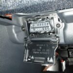
First, you’ll need to open up the OBD2 scanner’s enclosure. Start by carefully peeling off any sticker that might be covering the screws. Underneath, you’ll find four small screws, typically requiring a star screwdriver. Remove these screws to access the circuit board inside.
Once open, you’ll see the circuit board. Locate the ELM327 chip and the USB bridge chip. The key is to find the TX (Transmit) and RX (Receive) pins on the board, which are used for serial communication. Consult the pin-out diagram for the USB bridge chip, which is often readily available online by searching for the chip’s part number. These pins are usually clearly labeled or identifiable on the PCB.
Carefully solder two wires to the identified TX and RX pins. Precision is important here to avoid damaging any small components nearby. A helpful tip to ensure you’re connecting to the correct pins is to use an Arduino running a simple serial output sketch. Connect a jumper wire to the Arduino’s TX pin and gently probe the pins on the OBD2 scanner board. When you touch the correct RX pin on the scanner, you should see serial data activity, often indicated by flickering LEDs on the board. While this method is less effective for identifying the TX pin, the board layout and online resources should clearly indicate its location relative to the RX pin.
To ensure reliable communication with your Arduino and prevent conflicts, it’s recommended to disable the USB communication of the ELM327 scanner. The USB connection typically uses four pins. To isolate the serial communication for Arduino, carefully cut the middle two pins of the USB connector on the cable. This will prevent the scanner from attempting to communicate with a PC via USB while still allowing it to receive power, and freeing up the serial interface exclusively for your Arduino.
Finally, carefully reassemble the scanner. If the original enclosure is cumbersome for your project, you can simply tape it up or use alternative housing. With these modifications, your “basx obd2 scanner” is now ready to become a powerful interface for your Arduino car diagnostics and DIY automotive electronics projects, allowing you to directly access and utilize vehicle data for your creative endeavors.