Fuses are essential safety components in your 2001 Ford Ranger’s electrical system, protecting it from overloads that can damage sensitive parts. If you’re experiencing electrical issues in your Ranger, such as problems with your OBD2 port or other systems, checking the fuses should be one of your first steps. A blown fuse is often a simple fix that can save you time and money compared to more complex electrical repairs. This guide will help you locate the fuse boxes, identify the correct fuses, and understand how to check and replace them in your 2001 Ford Ranger.
To effectively troubleshoot electrical problems, it’s crucial to understand where the fuse panels are located in your 2001 Ford Ranger. There are two main fuse boxes: the passenger compartment fuse panel and the power distribution box, also known as the engine compartment fuse box. Knowing the location of each is the first step to diagnosing and resolving fuse-related issues.
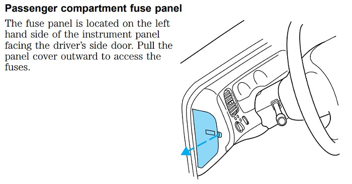
Passenger Compartment Fuse Panel
The passenger compartment fuse panel in a 2001 Ford Ranger is conveniently located inside the vehicle. Specifically, you’ll find it on the left end of the instrument panel. This location makes it easily accessible for quick checks and fuse replacements from within the cabin.
To get to the fuses, you’ll need to remove the fuse panel cover. You can do this by inserting your finger into the small divot or notch on the cover and gently pulling it outwards. Once removed, the underside of the cover is quite useful as it contains spare fuses for emergencies. Additionally, you’ll find a fuse pulling tool located in the lower right corner of the fuse panel itself, designed to assist in removing fuses without damaging them.
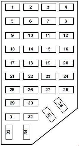
Here’s a chart detailing the fuses in the passenger compartment fuse panel of a 2001 Ford Ranger, outlining their amperage and the circuits they protect:
| No. | AMPS | Protected circuits |
|---|---|---|
| 1 | 5 | Power Mirror Switch |
| 2 | 10 | Daytime Running Lights (DRL), Back-up Lamps, Transmission, Passenger Air Bag Deactivation Switch, Blower Motor Relay |
| 3 | 7.5 | 2001-2002: Right Stop/Turn Trailer Tow Connector |
| 4 | — | Not Used |
| 5 | 15 | 4×4 Control Module |
| 6 | 2 | 2002-2003: Brake Pressure Switch |
| 7 | 7.5 | 2001-2002: Left Stop/Turn Trailer Tow Connector |
| 8 | — | Not Used |
| 9 | 7.5 | Brake Pedal Position Switch |
| 10 | 7.5 | Speed Control Servo/Amplifier Assembly, Generic Electronic Module (GEM), Shift Lock Actuator, Turn Signals, 4×4 |
| 11 | 7.5 | Instrument Cluster, 4×4, Main Light Switch, Truck Central Security Module (TCSM), GEM |
| 12 | — | Not Used |
| 13 | 20 | Brake Pedal Position Switch |
| 14 | 10 | ABS Control Module |
| 15 | — | Not Used |
| 16 | 30 | Windshield Wiper Motor, Wiper Hi-Lo Relay, Wiper Run/Park Relay |
| 17 | 20 | Cigar Lighter, Data Link Connector (DLC) |
| 18 | — | Not Used |
| 19 | 25 | Powertrain Control Module (PCM) Power Diode, Ignition, PATS |
| 20 | 7.5 | Generic Electronic Module (GEM), Radio |
| 21 | 15 | Flasher (Hazard) |
| 22 | 20 | Auxiliary Power Socket |
| 23 | — | Not Used |
| 24 | 7.5 | Clutch Pedal Position (CPP) switch, Starter Interrupt Relay |
| 25 | — | Not Used |
| 26 | 10 | Battery Saver Relay, Auxiliary Relay Box, Restraint Central Module (RCM), Generic Electroic Module (GEM), Instrument Cluster |
| 27 | — | Not Used |
| 28 | 7.5 | Generic Electronic Module (GEM), Radio |
| 29 | 20 | Radio |
| 30 | — | Not Used |
| 31 | — | Not Used |
| 32 | — | Not Used |
| 33 | 15 | Headlamps, Daytime Running Lamps (DRL) Module, Instrument Cluster |
| 34 | — | Not Used |
| 35 | 15 | Horn Relay if Not Equipped with Truck Central Security Module |
| 36 | — | Not Used |

Notably, Fuse #17 (20 AMP) protects the Data Link Connector (DLC), which is your OBD2 port. If you are experiencing issues connecting your OBD2 scanner, this fuse should be one of the first you inspect.
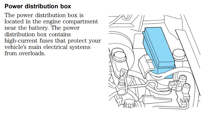
Power Distribution Box
The power distribution box in your 2001 Ford Ranger is situated in the engine compartment. Look for it on the driver’s side, near the fender. This box houses fuses and relays that manage higher-current electrical systems of your vehicle.
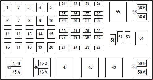
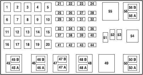
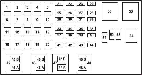
For a more specific visual, here are diagrams illustrating the power distribution box layout for different 2001 Ford Ranger engine types:
2.3L Engine (above)
3.0L & 4.0L Engines (2001)(above)
3.0L & 4.0L Engines (2002-2003)(above)
Below is a chart outlining the fuses and relays within the power distribution box of a 2001 Ford Ranger, along with their amperage and protected circuits:
| No. | AMP | Protected circuits |
|---|---|---|
| 1 | 50 | I/P Fuse Panel |
| 2 | 50 | Amplifier (Tremor audio system only) |
| 3 | — | Not Used |
| 4 | — | Not Used |
| 5 | — | Not Used |
| 6 | 50 | ABS Pump Motor |
| 7 | 30 | Powertrain Control Module (PCM) |
| 8 | 20 | Power Door Locks and Remote Entry |
| 9 | — | Not Used |
| 10 | — | Not Used |
| 11 | 50 | Starter Relay, Ignition Switch |
| 12 | 20 | Power Windows |
| 13 | 20 | 3.0L and 4.0L engines: 4×4 Motor |
| 14 | — | Not Used |
| 15 | — | Not Used |
| 16 | 40 | Blower Motor |
| 17 | 20 | 2.3L engine: Auxiliary Cooling Fan |
| 18 | — | Not Used |
| 19 | — | Not Used |
| 20 | — | Not Used |
| 21 | 10 | PCM Memory |
| 22 | — | Not Used |
| 23 | 20 | Fuel Pump Motor |
| 24 | 30 | Headlamps |
| 25 | 10 | A/C Clutch Solenoid |
| 26 | — | Not Used |
| 27 | — | Not Used |
| 28 | 30 | 4WABS Module |
| 29 | — | Not Used |
| 30 | 15 | Trailer Tow |
| 31 | 20 | Foglamps, Daytime Running Lamps (DRL) |
| 32 | — | Not Used |
| 33 | 15 | Park Lamp |
| 34 | — | Not Used |
| 35 | — | Not Used |
| 36 | — | Not Used |
| 37 | — | Not Used |
| 38 | 10 | Left Headlamp Low Beam |
| 39 | — | Not Used |
| 40 | — | Not Used |
| 41 | 20 | Heated Oxygen Sensors |
| 42 | 10 | Right Headlamp Low Beam |
| 43 | — | 2.3L engine: (Resistor) |
| 44 | — | Not Used |
| 51 | — | Not Used |
| 52 | — | Not Used |
| 53 | — | Diode: Powertrain Control Module (PCM) |
| Relay | ||
| 45A | Wiper HI/LO | |
| 45B | Wiper Park/Rim | |
| 46A | 2.3L engine: Fuel Pump 3.0L and 4.0L engines (2002-2003): Fuel Pump | |
| 46B | 2.3L engine: Trailer Tow 3.0L and 4.0L engines (2001): Front Washer Pump 3.0L and 4.0L engines (2002-2003): Trailer tow | |
| 47 | 2.3L engine: Starter 3.0L and 4.0L engines (2001): A/B – Not Used | |
| 47A | 3.0L and 4.0L engines (2002-2003): A/C clutch solenoid | |
| 47B | 3.0L and 4.0L engines (2002-2003): Front washer pump | |
| 48 | 2.3L engine: Auxiliary Cooling Fan | |
| 48A | 3.0L and 4.0L engines: Fog Lamps | |
| 48B | 3.0L and 4.0L engines: Fog Lamp Relay | |
| 49 | 3.0L and 4.0L engines (2001): Starter | |
| 50 | Not Used | |
| 50A | 3.0L and 4.0L engines (2001): Not Used | |
| 50B | 3.0L and 4.0L engines (2001): Fuel Pump | |
| 54 | Powertrain Control Module (PCM) | |
| 55 | Blower | |
| 56 | 3.0L and 4.0L engines (2002-2003): Starter | |
| 56A | A/C Clutch Solenoid | |
| 56B | 2.3L engine: Front Washer Pump 3.0L and 4.0L engines (2001): Trailer Tow |
Checking and Replacing Fuses: A Step-by-Step Guide
Once you have located the relevant fuse panel and identified the fuse you suspect is blown, follow these steps to check and replace it:
-
Access the Fuse Panel: For the passenger compartment fuse panel, it’s inside the vehicle on the left side of the dashboard. Remove the cover as described earlier. For the power distribution box, open the hood and locate the box on the driver’s side of the engine compartment.
-
Identify the Fuse to Check: Consult the fuse panel cover or the diagrams provided in this guide to find the number of the fuse associated with the circuit you are troubleshooting, such as the OBD2 port fuse (Fuse #17 in the passenger compartment).
-
Visually Inspect the Fuse: Look at the fuse. Each fuse has a clear plastic housing, allowing you to see the internal wire. Check if the thin metal wire inside the fuse is broken or melted. If the wire is separated, the fuse is blown and needs replacement.
-
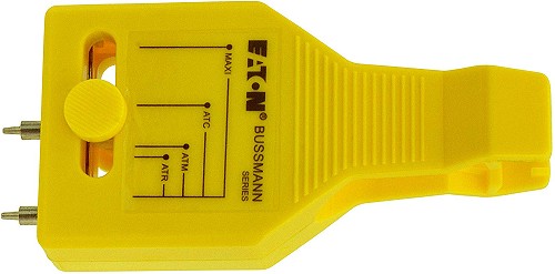
Use a Fuse Tester (Optional but Recommended): For a more definitive check without removing the fuse, a fuse tester like a Bussmann fuse tester is very helpful. Simply align the tester prongs with the metal test points on top of the fuse. If the indicator light illuminates, the fuse is good. If it doesn’t light up, the fuse is likely blown.
Alt text: Bussmann fuse tester being used to check a car fuse, showing the tester connected to the fuse terminals.
-
Replace the Blown Fuse: If the fuse is blown, use the fuse puller tool (if available in your fuse box, or pliers if not) to carefully remove the blown fuse. Take a spare fuse of the exact same amperage rating from the fuse panel cover or your spare fuse kit. Important WARNING: Always replace a fuse with one of the specified amperage rating. Using a fuse with a higher rating can lead to serious wire damage and increase the risk of fire. Push the new fuse firmly into the fuse slot.
-
Replace the Fuse Panel Cover: Once the fuse is replaced, put the fuse panel cover back in place to protect the fuses.
-
Test the Circuit: After replacing the fuse, test the electrical component that was not working to see if it now functions correctly. For example, if you replaced the OBD2 fuse, try connecting your OBD2 scanner again.
-
Troubleshooting Persistent Blown Fuses: If the new fuse blows immediately or shortly after replacement, it indicates a persistent problem in the circuit, such as a short circuit or overload. In this case, further diagnosis by a qualified automotive technician is recommended to identify and repair the underlying issue. Repeatedly replacing fuses without addressing the root cause can be dangerous and may cause further damage.
Understanding Fuse Colors and Ratings
Fuses are color-coded to easily identify their amperage rating. This standardization helps ensure you use the correct replacement fuse. Here’s a common color-coding guide for fuses:
- Red: 10 Amp
- Blue: 15 Amp
- Natural/Clear: 20 Amp
- Light Green: 30 Amp
Always match the color and amperage rating of the fuse you are replacing to ensure proper circuit protection and prevent electrical system damage in your 2001 Ford Ranger. By understanding your 2001 Ford Ranger’s fuse system and following these steps, you can effectively diagnose and resolve many common electrical issues, including problems related to your OBD2 system.