Like many, I’ve always used cars without fully grasping the intricate workings beneath the hood. Beyond basic maintenance like air filter replacement or oil changes, the engine remained a mystery. However, a desire to understand the core technology I rely on daily sparked a journey into automotive mechanics. If you’re like me – someone who isn’t a “car guy” but is curious about what makes your vehicle tick – this guide is for you. We’ll delve into the heart of your car: the internal combustion engine.
The Inner Workings of the Internal Combustion Engine
The term “internal combustion engine” itself is quite descriptive. It signifies that the combustion of fuel and air occurs inside the engine. This controlled explosion is the driving force behind your car, generating energy that moves pistons and ultimately propels your vehicle.
This contrasts with external combustion engines, like steam engines, where fuel is burned outside the engine to heat water and create steam, which then powers the mechanism. Interestingly, despite the common perception that steam engines preceded internal combustion engines in the history of mechanized movement, the internal combustion concept actually came first. Early iterations, dating back to the 16th century, experimented with gunpowder as fuel. These atmospheric engines relied on vacuum pressure created after gunpowder explosions to move pistons, but they were inefficient and soon overshadowed by the promising advancements in steam engine technology by the 17th century.
It wasn’t until 1860 that Jean Joseph Etienne Lenoir, a Belgian inventor, patented a practical internal combustion engine. Lenoir’s engine used natural gas ignited by a nearby flame to drive a piston, a step forward but still not highly efficient. Building on Lenoir’s work, German engineers Nicolaus August Otto and Eugen Langen developed similar engines. Otto later refined his designs, culminating in the four-stroke engine in 1864. This revolutionary design, the foundation of modern car engines, remains in use today.
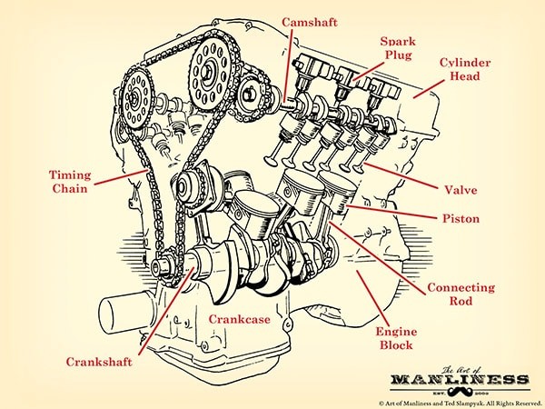
Exploring the Anatomy of a Car Engine: Parts Diagram Explained
Before diving into the four-stroke cycle, let’s familiarize ourselves with the key components of a car engine. Understanding these parts will provide context as we explore the engine’s operational process. Don’t worry if some terms seem unfamiliar initially; read through the entire section to get a general overview, then revisit for a deeper understanding of each part.
Engine Block (Cylinder Block): The Foundation
The engine block, often called the cylinder block, serves as the engine’s structural backbone. Typically cast from aluminum alloy (though some manufacturers still use iron), it’s essentially a solid piece of metal with hollow cylinders integrated within. These cylinders are crucial pathways where pistons move up and down. The number of cylinders is often directly related to engine power – more cylinders generally mean a more powerful engine. Beyond cylinders, the block also houses internal passages for oil and coolant circulation, essential for engine lubrication and temperature regulation.
Decoding Engine Designations: V6 and V8 Explained
The terms “V6” or “V8” refer to the engine’s cylinder configuration and quantity. Inline engines, often found in four-cylinder configurations, arrange cylinders in a straight line above the crankshaft. “Flat-four” engines are another four-cylinder layout, positioning cylinders horizontally in two banks along a central crankshaft.
Engines with more than four cylinders often adopt a “V” shape, dividing cylinders into two banks. A V6 engine has six cylinders arranged in a V shape (three cylinders per bank), while a V8 engine features eight cylinders (four per bank). This V configuration helps in engine packaging and balance.
Combustion Chamber: Where Power is Born
The combustion chamber is the epicenter of engine power generation. This is where fuel, air, compression, and ignition converge to create the controlled explosion that drives the pistons. It’s defined by the cylinder walls, the piston top (acting as the chamber floor), and the cylinder head (forming the ceiling).
Cylinder Head: Sealing the Combustion
Positioned above the engine cylinders, the cylinder head is a metal component with indentations that provide space for combustion. A critical component called the head gasket ensures a tight seal between the cylinder head and engine block, preventing leaks. The cylinder head also serves as a mounting point for intake and exhaust valves, spark plugs, and fuel injectors, all vital for the combustion process.
Piston: The Moving Force
Pistons are cylindrical components that move vertically within the cylinders. Shaped like inverted soup cans, they are pushed downwards by the force of combustion, transferring this linear motion to the crankshaft. Each piston is connected to the crankshaft via a connecting rod (or con rod) and a piston pin. The connecting rod, in turn, attaches to the crankshaft using a connecting rod bearing.
Pistons are equipped with piston rings, located in grooves around their circumference. These rings, made of iron, come in two types: compression rings and oil rings. Compression rings, the top rings, press against the cylinder walls, creating a tight seal within the combustion chamber. Oil rings, positioned lower, prevent oil from the crankcase from entering the combustion chamber and scrape excess oil from the cylinder walls back into the crankcase for lubrication.
Crankshaft: Converting Linear to Rotational Motion
The crankshaft is the ingenious component that transforms the piston’s up-and-down motion into the rotational motion necessary to drive the car. It sits lengthwise within the engine block, typically near the bottom, extending from one end to the other. At the front, it connects to belts that power components like the camshaft and other accessories. At the rear, it links to the drivetrain, which transmits power to the wheels. Oil seals (O-rings) at each end prevent oil leakage.
The crankshaft resides in the crankcase, located below the cylinder block, which protects it and the connecting rods. The lower part of the crankcase is the oil pan, the engine’s oil reservoir. Inside the oil pan, an oil pump circulates oil through a filter and then to the crankshaft, connecting rod bearings, and cylinder walls, ensuring lubrication for piston movement. The oil then returns to the oil pan, completing the cycle.
Balancing lobes along the crankshaft act as counterweights, minimizing vibrations and preventing damage during high-speed rotation. Main bearings provide smooth contact surfaces between the crankshaft and engine block, facilitating free rotation.
Camshaft: Orchestrating Valve Timing
Often referred to as the engine’s “brain,” the camshaft works in sync with the crankshaft via a timing belt or chain. Its crucial role is to precisely control the opening and closing of intake and exhaust valves for optimal engine performance. Egg-shaped lobes along the camshaft dictate valve timing.
In most engines, the camshaft is positioned above the crankshaft in the upper engine block. Inline engines typically use a single camshaft for both intake and exhaust valves. V-shaped engines often employ two camshafts, one for each cylinder bank. Some advanced V-engines even use dual camshafts per bank, allowing for more precise valve control.
Timing System: Synchronization is Key
The timing system, consisting of a timing belt or chain, ensures the crankshaft and camshaft rotate in perfect synchronization. This precise coordination is critical for proper valve timing. If the timing belt or chain slips, causing misalignment, the engine will malfunction.
Valvetrain: Controlling Air and Exhaust Flow
The valvetrain is a mechanical system mounted on the cylinder head that governs valve operation. It comprises valves, rocker arms, pushrods, and lifters.
Valves: Intake and Exhaust Control
Engines utilize two types of valves: intake valves and exhaust valves. Intake valves allow the air-fuel mixture to enter the combustion chamber for combustion. Exhaust valves then release the resulting exhaust gases after combustion.
Typically, engines have at least one intake and one exhaust valve per cylinder. High-performance engines often feature four valves per cylinder (two intake, two exhaust) for improved airflow, enhancing engine efficiency. Some designs even use three valves per cylinder (two intake, one exhaust). Multi-valve systems optimize engine “breathing,” leading to better performance.
Rocker Arms: Valve Levers
Rocker arms are small levers that interact with the camshaft lobes. As a lobe rotates and lifts one end of the rocker arm, the other end presses down on the valve stem, opening the valve. This see-saw motion controls valve opening and closing.
Pushrods/Lifters: Bridging the Gap
In overhead camshaft (OHC) engines, camshaft lobes often directly actuate rocker arms. However, overhead valve (OHV) engines require pushrods or lifters to transmit motion from the camshaft lobes to the rocker arms.
Fuel Injectors: Delivering Fuel for Combustion
Fuel is essential for combustion. Modern cars utilize fuel injection systems instead of older carburetors. Three main types of fuel injection systems exist:
- Direct Fuel Injection: Each cylinder has its own injector that sprays fuel directly into the combustion chamber at the optimal moment.
- Ported Fuel Injection: Fuel is injected into the intake manifold, just outside the intake valve. When the valve opens, the air-fuel mixture enters the cylinder.
- Throttle Body Fuel Injection: A single injector in the throttle body mixes fuel with air before distribution to cylinders via intake valves, similar to carburetors but without the carburetor itself.
Spark Plug: Initiating Combustion
Located above each cylinder, the spark plug generates a spark to ignite the compressed air-fuel mixture, initiating the power-producing explosion.
The Four-Stroke Cycle: The Engine’s Rhythm
Now that we’ve explored the engine’s components using a Car Engine Parts Diagram, let’s understand how they work together in the four-stroke cycle – the fundamental process that powers your car.
The illustration below depicts the four-stroke cycle within a single cylinder. This cycle occurs simultaneously in all cylinders, repeating hundreds or thousands of times per minute, driving your vehicle.
- Intake Stroke: The piston moves downwards, creating a vacuum in the cylinder. The intake valve opens, allowing the air-fuel mixture to be drawn into the combustion chamber.
- Compression Stroke: The intake valve closes, and the piston moves upwards, compressing the air-fuel mixture. This compression increases the mixture’s temperature and readiness for combustion.
- Combustion (Power) Stroke: As the piston reaches the top of its stroke, the spark plug ignites the compressed air-fuel mixture. The resulting explosion forces the piston downwards, generating power.
- Exhaust Stroke: The exhaust valve opens, and the piston moves upwards again, pushing the burnt exhaust gases out of the combustion chamber.
This cycle then repeats continuously, providing the power to move your car.
This overview provides a foundational understanding of how a car engine operates. Take some time to look under the hood of your car and try to identify the parts we’ve discussed. For further in-depth learning, consider resources like “How Cars Work,” a helpful guide for beginners seeking a more detailed explanation.