Have you ever wondered what goes on under the hood of your car? For many, the engine remains a mysterious black box, understood only by mechanics. Like the author of the original article, I used to nod along politely when my mechanic explained issues, secretly wishing I had a better grasp of the fundamentals. As a content creator at carparteu.com and a car repair enthusiast, I believe that understanding the basics of your car engine is not just for “car guys.” It empowers you to communicate more effectively with mechanics, make informed decisions about car maintenance, and simply appreciate the marvel of engineering that powers your daily commute.
This guide will break down the basics of car engine parts, focusing on the internal combustion engine – the heart of most vehicles on the road today. We’ll explore the key components and how they work together to convert fuel into motion. Whether you’re a complete beginner or just looking to refresh your knowledge, this article will provide a clear and concise overview of the essential parts of a car engine.
What is an Internal Combustion Engine?
The term “internal combustion engine” might sound complex, but it simply refers to an engine where fuel and air are burned inside the engine itself. This combustion process generates energy, which is then used to move pistons and ultimately propel your car.
This is different from an “external combustion engine,” like a steam engine, where fuel is burned outside the engine to heat water and create steam that drives the engine. While steam engines historically preceded internal combustion engines, the latter quickly became dominant due to their efficiency and power-to-weight ratio.
Early forms of internal combustion engines experimented with gunpowder. These atmospheric engines relied on the vacuum created after a gunpowder explosion to move a piston. However, they were inefficient and soon overtaken by the promise of steam power. It wasn’t until 1860 that Jean Joseph Etienne Lenoir patented a more practical internal combustion engine using natural gas. Building on this, Nicolaus August Otto developed the four-stroke engine in 1864, a design that remains the foundation of modern car engines.
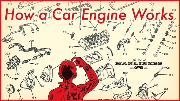
Alt text: Diagram illustrating how a car engine works, showcasing the main components and their interaction.
Exploring the Anatomy: Key Car Engine Parts
To understand how a car engine functions, let’s delve into the anatomy and explore the essential parts. Think of the engine as a complex system, where each component plays a crucial role in the overall process.
1. Engine Block (Cylinder Block): The Foundation
The engine block is the structural core of the engine. Often made from aluminum alloy or cast iron, it’s also known as the cylinder block because it houses the cylinders – hollow tubes where pistons move. The number of cylinders generally correlates with engine power. Beyond cylinders, the block contains channels for oil and coolant circulation, essential for engine lubrication and temperature regulation.
Decoding Engine Designations: V6 and V8 Engines
Engine designations like “V6” or “V8” refer to the cylinder arrangement and count. Inline engines, common for four-cylinder configurations, have cylinders aligned in a straight row above the crankshaft. Flat-four engines also exist, with horizontally opposed cylinders. When engines have more than four cylinders, they are typically arranged in two banks, forming a “V” shape. A V6 engine has six cylinders in a V formation (three per bank), and a V8 engine has eight cylinders (four per bank).
2. Combustion Chamber: The Powerhouse
The combustion chamber is where the energy is generated. This is where fuel, air, compression, and ignition combine to create a controlled explosion that drives the pistons. The combustion chamber is formed by the cylinder walls, the piston top (acting as the floor), and the cylinder head (serving as the ceiling).
3. Cylinder Head: Sealing and Control
The cylinder head is a metal component that sits atop the engine block, sealing the cylinders. It features indentations to create space for combustion at the top of the chamber. A head gasket ensures a tight seal between the cylinder head and block. Crucially, the cylinder head also houses intake and exhaust valves, spark plugs, and fuel injectors, which we’ll discuss further.
4. Piston: The Moving Force
Pistons are cylindrical components that move vertically within the cylinders. When combustion occurs, the expanding gases force the piston downwards. This linear motion is then converted into rotational motion. Each piston connects to the crankshaft via a connecting rod (or con rod) and a piston pin. The connecting rod, in turn, attaches to the crankshaft using a connecting rod bearing.
Pistons are equipped with piston rings inserted into grooves on their outer surface. These rings, typically made of iron, are crucial for sealing the combustion chamber and controlling oil. Compression rings, located at the top, create a tight seal against the cylinder walls to maximize combustion pressure. Oil rings, at the bottom, prevent oil from entering the combustion chamber and scrape excess oil back into the crankcase.
5. Crankshaft: Converting Linear to Rotational Motion
The crankshaft is the component that transforms the piston’s up-and-down motion into the rotational motion that powers the car’s wheels. It’s positioned lengthwise within the engine block, usually at the bottom. At the front, it connects to belts that drive components like the camshaft, while at the rear, it links to the drivetrain, transferring power to the wheels. Oil seals (O-rings) at each end prevent oil leakage.
The crankshaft resides in the crankcase, located beneath the cylinder block, which protects it and the connecting rods. The oil pan, at the bottom of the crankcase, stores the engine oil. An oil pump within the pan circulates oil through a filter and then to critical engine parts like the crankshaft bearings, connecting rod bearings, and cylinder walls for lubrication. The oil then drains back into the oil pan to repeat the cycle.
Balancing lobes along the crankshaft act as counterweights, minimizing vibrations during rotation. Main bearings provide smooth surfaces between the crankshaft and engine block, allowing for free rotation.
6. Camshaft: The Engine’s Brain
The camshaft is responsible for precisely controlling the timing of valve opening and closing, crucial for optimal engine performance. Working in sync with the crankshaft via a timing belt or chain, the camshaft uses egg-shaped lobes to actuate the valves.
Typically located in the upper part of the engine block, above the crankshaft, camshaft configurations vary. Inline engines often use a single camshaft for both intake and exhaust valves. V-shaped engines may have two camshafts (one per cylinder bank) or even four (two per bank), offering more precise valve control.
7. Timing System: Synchronization is Key
The timing belt or chain synchronizes the crankshaft and camshaft, ensuring they rotate in precise relation to each other. This synchronization is vital for proper engine operation. If the timing is disrupted (e.g., the timing chain skips), the engine will malfunction.
8. Valvetrain: Controlling Air and Exhaust Flow
The valvetrain is a mechanical system mounted on the cylinder head that manages the opening and closing of valves. It consists of valves, rocker arms, pushrods (in some designs), and lifters.
9. Valves: Intake and Exhaust
Engines have two types of valves: intake and exhaust. Intake valves allow the air-fuel mixture to enter the combustion chamber, while exhaust valves let combustion gases escape. Most cars have at least one intake and one exhaust valve per cylinder. High-performance engines, and even some mainstream brands like Honda, often employ multi-valve systems (e.g., four valves per cylinder – two intake and two exhaust) to improve engine “breathing” and performance. Three-valve systems (two intake, one exhaust) also exist.
10. Rocker Arms: Valve Actuation Levers
Rocker arms are small levers that interact with the camshaft lobes. As a lobe rotates and lifts one end of the rocker arm, the other end presses down on the valve stem, opening the valve. This see-saw action controls valve timing.
11. Pushrods and Lifters: Connecting Camshaft to Rocker Arms (Overhead Valve Engines)
In overhead valve engines, where the camshaft is located lower in the engine block, pushrods and lifters are used to transmit motion from the camshaft lobes to the rocker arms. In overhead camshaft engines, the camshaft lobes directly actuate the rocker arms, eliminating the need for pushrods.
12. Fuel Injectors: Delivering the Fuel
Fuel injectors are responsible for delivering fuel into the engine cylinders. Modern cars primarily use fuel injection systems, replacing older carburetors. Common types include:
- Direct Fuel Injection: Injectors spray fuel directly into each cylinder’s combustion chamber for precise fuel delivery.
- Ported Fuel Injection: Fuel is injected into the intake manifold, just outside the intake valves, mixing with air before entering the cylinder.
- Throttle Body Fuel Injection: A single injector supplies fuel to a throttle body, where it mixes with air and is then distributed to the cylinders.
13. Spark Plug: Ignition Spark
Each cylinder has a spark plug, positioned above it. The spark plug generates an electrical spark that ignites the compressed air-fuel mixture in the combustion chamber, initiating the power stroke.
Alt text: Detailed diagram of a V8 engine, highlighting various engine parts like cylinder head, pistons, crankshaft, and camshaft.
The Four-Stroke Cycle: The Engine’s Rhythm
Now that we’ve examined the key parts, let’s understand how they work together in the four-stroke cycle, the sequence of events that produces engine power. This cycle repeats continuously in each cylinder, thousands of times per minute, driving your car.
The Four Strokes:
- Intake Stroke: The piston moves down, drawing a mixture of air and fuel into the cylinder through the open intake valve.
- Compression Stroke: The intake valve closes, and the piston moves upwards, compressing the air-fuel mixture. This compression increases the mixture’s temperature and prepares it for combustion.
- Combustion (Power) Stroke: The spark plug ignites the compressed air-fuel mixture. The resulting explosion forces the piston downwards, generating power.
- Exhaust Stroke: The exhaust valve opens, and the piston moves upwards, pushing the exhaust gases out of the cylinder.
Alt text: Illustration depicting the four-stroke cycle of an internal combustion engine: Intake, Compression, Combustion, and Exhaust.
Conclusion: Engine Basics Unveiled
Understanding the basics of car engine parts can seem daunting at first, but breaking it down into manageable components makes it much clearer. By familiarizing yourself with these fundamental parts and the four-stroke cycle, you’ve taken a significant step towards demystifying the engine.
Take some time to look under the hood of your car and see if you can identify some of the parts we’ve discussed. Further exploration through resources like “How Cars Work” can deepen your understanding. Armed with this knowledge, you’ll be better equipped to understand your car and communicate with mechanics, transforming from a passive observer to an informed car owner.