Need a clear and in-depth understanding of CAN OBD2 for vehicle diagnostics?
This guide provides an expert look into the On-Board Diagnostic (OBD2) protocol, specifically focusing on its integration with the Controller Area Network (CAN bus). We’ll explore the OBD2 connector, OBD2 Parameter IDs (PIDs), and the crucial link to CAN bus communication in modern vehicles.
As a content creator for carparteu.com and a specialist in automotive repair, I aim to deliver a superior, SEO-optimized resource for the English-speaking market. This article goes beyond a basic introduction, offering practical insights into requesting and interpreting CAN OBD2 data, key use cases, and valuable tips for professionals and enthusiasts alike.
Discover why this article is set to become your go-to guide for mastering CAN OBD2 diagnostics.
You can also watch introductory videos on OBD2 and CAN bus on carparteu.com’s video resources or download our comprehensive PDF guide available on our website.
Understanding OBD2 and its Relation to CAN
OBD2 is essentially your car’s internal health monitoring system. It’s a standardized protocol designed to access diagnostic trouble codes (DTCs) and real-time vehicle data through the OBD2 port.
You’re likely already familiar with OBD2 in some form:
Ever seen the check engine light illuminate on your dashboard?
That’s your vehicle signaling a potential problem. When you take your car to a mechanic, they use a CAN OBD2 scanner to pinpoint the issue.
This involves connecting the OBD2 scanner to the 16-pin OBD2 connector, typically located near the steering wheel. The scanner sends ‘CAN OBD2 requests’ to the car’s computer, and the car responds with ‘CAN OBD2 responses’. These responses can contain vital information such as speed, fuel level, and Diagnostic Trouble Codes (DTCs), significantly speeding up the diagnostic process.
Alt text: Malfunction Indicator Light (MIL) illuminates on a car dashboard, indicating an issue detectable via OBD2 scan tool.
OBD2 Compatibility: Does Your Car Support CAN OBD2?
In most cases, yes!
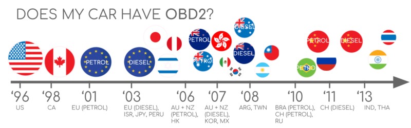
The vast majority of modern gasoline and diesel cars, excluding electric vehicles in some respects, are equipped with CAN OBD2. While older vehicles might feature a 16-pin OBD2 connector, it’s not guaranteed to support the full CAN OBD2 protocol. Compliance is often determined by the vehicle’s region and year of manufacture:
Alt text: Chart showing OBD2 compliance by region (EU, US) and vehicle type, highlighting mandatory years for gasoline, diesel cars and light trucks.
A Brief History of CAN OBD2
The origins of OBD2 trace back to California, where the California Air Resources Board (CARB) mandated OBD systems in all new cars from 1991 onwards for emissions monitoring.
The Society of Automotive Engineers (SAE) played a key role in standardizing OBD2, particularly defining Diagnostic Trouble Codes (DTCs) and the universal OBD connector (SAE J1962).
The adoption of the CAN OBD2 standard progressed in stages:
- 1996: CAN OBD2 became mandatory in the USA for cars and light trucks.
- 2001: The EU required CAN OBD2 for gasoline vehicles.
- 2003: EU legislation extended CAN OBD2 requirements to diesel vehicles (EOBD).
- 2005: CAN OBD2 was mandated in the US for medium-duty vehicles.
- 2008: US vehicles were required to use ISO 15765-4 (CAN) as the foundation for CAN OBD2.
- 2010: CAN OBD2 became mandatory for heavy-duty vehicles in the US.
Alt text: OBD2 history infographic emphasizing emission control, exhaust standards, EOBD2, and CAN bus integration for vehicle data.
Alt text: Timeline overview of OBD2 history, highlighting key milestones in on-board diagnostics development and standardization.
Alt text: Graphic depicting OBD3 future trends, including remote diagnostics, emissions testing, cloud connectivity, and IoT integration for on-board diagnostics.
The Future of CAN OBD2
While CAN OBD2 remains relevant, its future is evolving. Key trends include:
Initially designed for emissions control, regulatory CAN OBD2 requirements don’t strictly apply to electric vehicles. Consequently, many modern EVs lack standard CAN OBD2 support, opting instead for OEM-specific UDS communication protocols. This often complicates data access from EVs, requiring reverse engineering efforts to decode proprietary data formats. However, resources are emerging, including case studies for electric cars like Tesla, Hyundai/Kia, Nissan, and VW/Skoda EVs, which explore methods to access and interpret data from these vehicles.
CAN OBD2, despite its widespread use, has limitations in data richness and protocol flexibility. In response, newer standards like WWH-OBD (World Wide Harmonized OBD) and OBDonUDS (OBD on UDS) are emerging. These aim to modernize OBD communication by utilizing the UDS protocol as a foundation, offering enhanced capabilities. For a deeper understanding of these advancements, refer to resources detailing the UDS protocol.
In the age of connected vehicles, traditional CAN OBD2 emission tests are becoming less efficient. OBD3 proposes incorporating telematics into all vehicles.
OBD3 envisions adding a small radio transponder to vehicles, similar to those used for electronic toll collection. This would enable automatic transmission of the vehicle identification number (VIN) and DTCs via WiFi to a central server for remote monitoring.
Current technologies, such as the CANedge2 WiFi CAN logger and CANedge3 3G/4G CAN logger, already facilitate CAN and CAN OBD2 data transfer over wireless networks.
While offering convenience and cost savings, OBD3 raises privacy concerns related to vehicle surveillance.
While CAN OBD2 was initially intended for in-garage vehicle servicing, its use has expanded significantly to third-party real-time data applications via CAN OBD2 dongles, CAN loggers, and similar devices. However, the automotive industry is considering changes that could impact this landscape:
“OBD has been designed to service cars in repair shops. In no way has it been intended to allow third parties to build a form of data-driven economy on the access through this interface“
– Christoph Grote, SVP Electronics, BMW (2017)
Proposals suggest disabling CAN OBD2 functionality during normal driving, centralizing data collection through manufacturer-controlled servers. This would give OEMs greater control over ‘automotive big data’.
Arguments for this shift include enhanced security, aiming to mitigate car hacking risks. However, many perceive this as a commercially motivated move to control the automotive data ecosystem. The future of CAN OBD2 third-party services remains uncertain as this trend develops.
Alt text: Illustration showing OBD2 connector removal from an electric vehicle, symbolizing restricted data access in EVs compared to traditional vehicles.
Enhance Your CAN Expertise
Ready to become a CAN bus expert?
Access our comprehensive “Ultimate CAN Guide,” compiling 12 essential introductions into a 160+ page PDF resource:
Download now
CAN OBD2 Standards: Protocols and Layers
On-board diagnostics, CAN OBD2, operates as a higher-layer protocol, functioning like a language built upon the communication method of CAN bus (similar to a phone line). CAN OBD2 is analogous to other CAN-based higher-layer protocols such as J1939, CANopen, and NMEA 2000.
CAN OBD2 standards define specifications for the OBD2 connector, lower-layer protocols, OBD2 Parameter IDs (PIDs), and more.
These standards can be categorized using the 7-layer OSI model. Notably, both SAE and ISO standards cover various layers, reflecting the standardization efforts in the USA (SAE) and EU (ISO). Many standards are technically similar, such as SAE J1979 and ISO 15031-5, or SAE J1962 and ISO 15031-3.
Alt text: OSI Model diagram comparing OBD2 and CAN Bus, highlighting ISO 15765 and ISO 11898 standards across the 7 layers.
Alt text: OBD2 Connector Pinout Socket diagram (Female Type A DLC) illustrating pin assignments for data link connector.
The CAN OBD2 Connector [SAE J1962]
The 16-pin CAN OBD2 connector, standardized under SAE J1962 / ISO 15031-3, provides straightforward access to your vehicle’s data.
The illustration shows a Type A OBD2 connector pinout (also known as Data Link Connector, DLC).
Key points about the CAN OBD2 connector:
- Usually located near the steering wheel, though it may be concealed.
- Pin 16 provides battery power, often active even when the ignition is off.
- The OBD2 pinout configuration depends on the communication protocol used.
- CAN bus is the most prevalent lower-layer protocol, typically utilizing pins 6 (CAN-H) and 14 (CAN-L).
CAN OBD2 Connector Types: A vs. B
You might encounter both Type A and Type B CAN OBD2 connectors. Type A is standard in cars, while Type B is more common in medium and heavy-duty vehicles.
While both types share similar CAN OBD2 pinouts, they differ in power supply output (12V for Type A and 24V for Type B) and often baud rates. Cars commonly use 500K baud rate, while heavy-duty vehicles often use 250K (with increasing support for 500K).
Visually, a Type B CAN OBD2 connector has a distinguishing interrupted groove in the middle. Consequently, a Type B OBD2 adapter cable is compatible with both Type A and Type B sockets, whereas a Type A adapter will not fit into a Type B socket.
Alt text: OBD2 Connector Type A versus Type B diagram, highlighting differences in SAE J1962 standards, voltage (12V/24V), and vehicle applications (car, van, truck).
Alt text: Diagram contrasting OBD2 and CAN bus, referencing ISO 15765 standard, and illustrating their relationship in vehicle diagnostics.
CAN OBD2 and CAN bus Integration [ISO 15765-4]
Since 2008, ISO 15765 mandates CAN bus as the lower-layer protocol for CAN OBD2 in all US vehicles.
ISO 15765-4, also known as Diagnostics over CAN (DoCAN), specifies constraints on the CAN standard (ISO 11898) for diagnostic communication.
Specifically, it standardizes the CAN interface for diagnostic equipment, focusing on the physical, data link, and network layers:
- CAN bus bit-rate must be 250K or 500K.
- CAN IDs can be 11-bit or 29-bit.
- Specific CAN IDs are designated for CAN OBD2 requests and responses.
- Diagnostic CAN frame data length is fixed at 8 bytes.
- The CAN OBD2 adapter cable must not exceed 5 meters in length.
CAN OBD2 Identifiers (11-bit, 29-bit)
All CAN OBD2 communication relies on request/response message exchanges.
In most cars, 11-bit CAN IDs are used for CAN OBD2. The ‘Functional Addressing’ ID is 0x7DF, used to query all CAN OBD2-compatible ECUs for data on a requested parameter (ISO 15765-4). CAN IDs in the range 0x7E0-0x7E7 are for ‘Physical Addressing’ requests to specific ECUs, though less commonly used.
ECUs respond using 11-bit IDs from 0x7E8 to 0x7EF. The most common response ID is 0x7E8 (ECM, Engine Control Module), followed by 0x7E9 (TCM, Transmission Control Module).
Some vehicles, particularly vans and medium to heavy-duty vehicles, may utilize extended 29-bit CAN identifiers for CAN OBD2 communication.
Here, the ‘Functional Addressing’ CAN ID is 0x18DB33F1.
Responses use CAN IDs from 0x18DAF100 to 0x18DAF1FF (typically 18DAF110 and 18DAF11E). The response ID is also sometimes presented as a J1939 PGN (Parameter Group Number), specifically PGN 0xDA00 (55808), which is marked in the J1939-71 standard as ‘Reserved for ISO 15765-2’.
Alt text: CAN OBD2 protocol request and response frames diagram, illustrating PID data parameters exchange in on-board diagnostics.
Alt text: Diagram contrasting OBD2 and proprietary CAN bus data, highlighting OEM-specific CAN data versus standardized OBD2 data access.
CAN OBD2 vs. Proprietary CAN Protocols
It’s important to recognize that vehicle ECUs operate using OEM-proprietary CAN protocols, not CAN OBD2. These proprietary protocols vary by vehicle brand, model, and year. Interpreting this OEM-specific CAN data is generally not possible without OEM documentation or reverse engineering.
Connecting a CAN bus data logger to your car’s CAN OBD2 port may reveal OEM-specific CAN data, often broadcast at high rates (1000-2000 frames/second). However, many newer vehicles employ a gateway that restricts access to this raw CAN data, allowing only CAN OBD2 communication through the OBD2 port.
Think of CAN OBD2 as an additional, higher-level protocol existing alongside the OEM-specific protocol.
Bit-rate and ID Validation in CAN OBD2
CAN OBD2 can use two bit-rates (250K, 500K) and two CAN ID lengths (11-bit, 29-bit), resulting in four potential combinations. Modern cars typically use 500K and 11-bit IDs. Diagnostic tools should systematically validate these parameters.
ISO 15765-4 outlines a systematic initialization sequence to determine the correct combination. This method relies on the requirement that CAN OBD2-compliant vehicles must respond to a specific mandatory CAN OBD2 request and the principle that incorrect bit-rate transmission will cause CAN error frames.
Newer versions of ISO 15765-4 account for CAN OBD2 communication via OBDonUDS as an alternative to OBDonEDS. This article primarily focuses on CAN OBD2/OBDonEDS (OBD on emission diagnostic service as per ISO 15031-5/SAE J1979) compared to WWH-OBD/OBDonUDS (OBD on Unified Diagnostic Service as per ISO 14229, ISO 27145-3/SAE J1979-2).
To differentiate between OBDonEDS and OBDonUDS, diagnostic tools may send UDS requests with 11-bit/29-bit functional address IDs for service 0x22 and data identifier (DID) 0xF810 (protocol identification). Vehicles supporting OBDonUDS should have ECUs that respond to this DID.
OBDonEDS (also known as OBD2, SAE OBD, EOBD, or ISO OBD) is prevalent in most non-EV cars today, while WWH-OBD is mainly used in EU trucks and buses.
Alt text: Flowchart illustrating CAN OBD2 bit-rate and CAN ID validation process according to ISO 15765-4 standards.
Alt text: Diagram outlining five lower-layer CAN OBD2 protocols: CAN (ISO 15765), KWP2000, SAE J1850, ISO9141, highlighting protocol diversity.
Five Lower-Layer CAN OBD2 Protocols
While CAN (ISO 15765) is now the dominant lower-layer protocol for CAN OBD2, especially in vehicles post-2008, older vehicles might use other protocols. Understanding these can be useful for diagnosing pre-2008 cars. The pinout of the OBD2 connector can sometimes indicate the protocol in use.
- ISO 15765 (CAN bus): Mandatory in US cars since 2008, widely used today.
- ISO14230-4 (KWP2000): Keyword Protocol 2000, common in 2003+ Asian cars.
- ISO 9141-2: Used in EU, Chrysler, and Asian cars (2000-04).
- SAE J1850 (VPW): Primarily used in older GM vehicles.
- SAE J1850 (PWM): Primarily used in older Ford vehicles.
ISO-TP for CAN OBD2 Message Transport [ISO 15765-2]
All CAN OBD2 data is transmitted over CAN bus using the ISO-TP (ISO 15765-2) transport protocol. This protocol allows for payloads exceeding the 8-byte CAN frame limit, essential for CAN OBD2 functions like retrieving Vehicle Identification Numbers (VINs) or Diagnostic Trouble Codes (DTCs). ISO 15765-2 manages segmentation, flow control, and reassembly of these larger messages. Detailed information can be found in resources explaining the UDS protocol.
However, much of CAN OBD2 data fits within a single CAN frame. In these cases, ISO 15765-2 specifies ‘Single Frame’ (SF) usage. Here, the first data byte (PCI field) indicates the payload length (excluding padding), leaving 7 bytes for CAN OBD2-related communication.
Alt text: ISO 15765-2 ISO-TP CAN OBD2 frame types diagram, illustrating Single Frame, First Frame, Consecutive Frame, and Flow Control frame formats.
Anatomy of a CAN OBD2 Diagnostic Message [SAE J1979, ISO 15031-5]
To better understand CAN OBD2 over CAN, let’s examine a raw ‘Single Frame’ CAN OBD2 CAN message. In simplified terms, a CAN OBD2 message consists of an identifier, data length (PCI field), and data. The data section is further divided into Mode, Parameter ID (PID), and data bytes.
Alt text: CAN OBD2 PIDs message structure breakdown diagram, explaining raw frame format with Mode, PID, ID, and data bytes.
Example: CAN OBD2 Request/Response
Consider a request/response example for ‘Vehicle Speed’.
A diagnostic tool sends a request message to the car with CAN ID 0x7DF, containing 2 payload bytes: Mode 0x01 and PID 0x0D. The car responds with CAN ID 0x7E8 and 3 payload bytes, with the Vehicle Speed value in the 4th byte, 0x32 (decimal 50).
Using CAN OBD2 PID decoding rules for PID 0x0D, we find that 0x32 corresponds to a physical value of 50 km/h.
Next, we’ll delve into CAN OBD2 modes and PIDs in more detail.
Alt text: CAN OBD2 request (7DF) and response (7E8) example diagram for vehicle speed PID, illustrating data flow in on-board diagnostics.
Alt text: CAN OBD2 PID example focusing on Vehicle Speed (PID 0D), detailing data interpretation and value representation.
Alt text: Diagram illustrating CAN OBD2 services (modes), including current data, freeze frame, and clear DTC functionalities in diagnostic services.
The 10 CAN OBD2 Services (Modes)
There are 10 standardized CAN OBD2 diagnostic services, or modes. Mode 0x01 provides real-time data, while others are used for Diagnostic Trouble Codes (DTCs) or freeze frame data.
Vehicles are not required to support all CAN OBD2 modes and may include OEM-specific modes beyond the 10 standard ones.
In CAN OBD2 messages, the mode is located in the second byte. In a request, the mode is included directly (e.g., 0x01), while in a response, 0x40 is added to the mode value (e.g., resulting in 0x41 for mode 0x01).
CAN OBD2 Parameter IDs (PIDs)
Each CAN OBD2 mode contains Parameter IDs (PIDs).
For example, mode 0x01 includes approximately 200 standardized PIDs for real-time data like speed, RPM, and fuel level. However, vehicles typically support only a subset of these PIDs.
One PID is particularly significant:
If an emissions-related ECU supports any CAN OBD2 services, it must support mode 0x01 PID 0x00. Responding to PID 0x00, the ECU indicates support for PIDs 0x01-0x20. This makes PID 0x00 a crucial ‘CAN OBD2 compatibility test’. Similarly, PIDs 0x20, 0x40, …, 0xC0 can be used to check support for subsequent mode 0x01 PIDs.
Alt text: CAN OBD2 protocol request and response frames diagram, emphasizing PID data parameters exchange in on-board diagnostics.
Alt text: CAN OBD2 PID overview tool interface, showcasing service 01 parameters for on-board diagnostics and data analysis.
Tip: CAN OBD2 PID Overview Tool
SAE J1979 and ISO 15031-5 appendices provide scaling information for standard CAN OBD2 PIDs, enabling data decoding into physical values.
For quick PID lookup in mode 0x01, utilize a CAN OBD2 PID overview tool. This assists in constructing CAN OBD2 request frames and dynamically decoding responses.
CAN OBD2 PID overview tool
Practical Guide: Logging and Decoding CAN OBD2 Data
This section offers a practical demonstration of CAN OBD2 data logging using the CANedge CAN bus data logger.
The CANedge allows configuration of custom CAN frames for transmission, making it suitable for CAN OBD2 logging.
Once set up, the CANedge easily connects to your vehicle via an OBD2-DB9 adapter cable.
Alt text: CAN OBD2 PID data logger request (7df) and response (7e8) diagram, illustrating data logging process for on-board diagnostics.
Alt text: asammdf screenshot displaying CAN OBD2 Supported PIDs Test responses, showcasing PID validation results in diagnostic data.
#1: Bit-rate, IDs & Supported PIDs Validation
ISO 15765-4 details how to determine the bit-rate and IDs for a specific vehicle. Use CANedge for testing:
- Transmit a CAN frame at 500K; check for success (if not, try 250K).
- Use the validated bit-rate for subsequent communication.
- Send multiple ‘Supported PIDs’ requests and analyze responses.
- Response IDs indicate 11-bit or 29-bit CAN IDs.
- Response data reveals supported PIDs.
Plug & play configurations for these tests are available.
Most post-2008 non-EV cars support 40-80 PIDs via 500K bit-rate, 11-bit CAN IDs, and CAN OBD2/OBDonEDS protocol.
As shown in the asammdf GUI screenshot, multiple responses to a single CAN OBD2 request are common due to the 0x7DF request ID polling all ECUs. Since all CAN OBD2/OBDonEDS-compliant ECUs must support service 0x01 PID 0x00, there are often numerous responses to this PID. Subsequent ‘Supported PIDs’ requests typically yield fewer ECU responses. Notice that the ECM ECU (0x7E8) supports all PIDs supported by other ECUs, reducing busload by directing subsequent requests to this specific ECU using ‘Physical Addressing’ CAN ID 0x7E0.
#2: Configuring CAN OBD2 PID Requests
Once you’ve identified supported CAN OBD2 PIDs, bit-rate, and CAN IDs, configure your transmit list with desired PIDs.
Consider these factors:
- CAN IDs: Use ‘Physical Addressing’ request IDs (e.g., 0x7E0) to minimize redundant responses.
- Spacing: Add 300-500 ms intervals between CAN OBD2 requests to avoid overwhelming ECUs.
- Battery Drain: Implement triggers to halt transmissions when the vehicle is inactive.
- Filters: Apply filters to record only CAN OBD2 responses, especially if OEM-specific CAN data is also present.
With these settings, your CANedge is ready for raw CAN OBD2 data logging.
Alt text: CANedge CAN OBD2 PID requests transmit list example, showing configured PIDs for data logging in on-board diagnostics.
Alt text: asammdf software visualizing decoded CAN OBD2 data plot using CAN bus DBC file, displaying diagnostic parameters graphically.
#3: DBC Decoding of Raw CAN OBD2 Data
To analyze and visualize logged data, decode raw CAN OBD2 data into physical values.
Decoding information is available in ISO 15031-5/SAE J1979 and online resources like Wikipedia. A free CAN OBD2 DBC file is available to facilitate DBC decoding in most CAN bus software tools.
Decoding CAN OBD2 data is more complex than standard CAN signals. Since different CAN OBD2 PIDs use the same CAN ID (e.g., 0x7E8), the CAN ID alone isn’t sufficient to identify payload signals.
Signal identification requires using the CAN ID, CAN OBD2 mode, and CAN OBD2 PID – a multiplexing form known as ‘extended multiplexing‘. This can be implemented in DBC files.
CANedge: Your CAN OBD2 Data Logger
The CANedge enables straightforward CAN OBD2 data recording onto 8-32GB SD cards. Simply connect to a vehicle to start logging and decode data using free software/APIs and the provided CAN OBD2 DBC file.
CAN OBD2 logger intro CANedge
CAN OBD2 Multi-Frame Examples [ISO-TP]
CAN OBD2 communication utilizes ISO-TP (ISO 15765-2), with most examples thus far showing single-frame communication. This section presents multi-frame communication examples.
Multi-frame CAN OBD2 requires flow control frames. A static flow control frame can be transmitted ~50ms post-request, as shown in the CANedge configuration example.
CANedge MF4 decoders and similar CAN software/API tools with ISO-TP support are necessary for processing multi-frame CAN OBD2 responses.
Alt text: CAN OBD2 multi-frame request message example for Vehicle Identification Number (VIN) retrieval, illustrating ISO-TP communication.
Example 1: CAN OBD2 Vehicle Identification Number (VIN) Retrieval
The Vehicle Identification Number (VIN) is crucial for telematics and diagnostics. To retrieve the VIN via CAN OBD2, use mode 0x09 and PID 0x02:
The diagnostic tool sends a Single Frame request with PCI field (0x02), service identifier (0x09), and PID (0x02).
The vehicle responds with a First Frame containing PCI, length (0x014 = 20 bytes), mode (0x49), and PID (0x02). Following the PID is byte 0x01 (Number Of Data Items – NODI). The subsequent 17 bytes are the VIN, translatable from HEX to ASCII.
Example 2: CAN OBD2 Multi-PID Request (6x)
Diagnostic tools can request up to 6 mode 0x01 CAN OBD2 PIDs in a single request frame. The ECU responds with data for supported PIDs (omitting unsupported ones), possibly across multiple frames via ISO-TP.
This method enhances data collection efficiency, but signal encoding becomes request-specific, complicating generic CAN OBD2 DBC file use. This approach is generally not recommended for practical use.
The multi-frame response resembles the VIN example, but the payload includes requested PIDs and their data. PIDs are often ordered as requested, though not strictly required by ISO 15031-5.
Decoding such responses via generic DBC files is complex and not recommended for practical data logging unless using tools with specific built-in support. Custom scripts could potentially handle this by interpreting responses in context of requests, but scalability is challenging.
Example 3: CAN OBD2 Diagnostic Trouble Codes (DTCs)
CAN OBD2 mode 0x03 (‘Show stored Diagnostic Trouble Codes’) retrieves emissions-related DTCs. The request contains no PID. Responding ECUs indicate the number of stored DTCs (possibly zero), with each DTC occupying 2 bytes. Multi-frame responses are necessary if more than two DTCs are stored.
The 2-byte DTC value is categorized and coded as per ISO 15031-5/ISO 15031-6. The first 2 bits define the ‘category’, and the remaining 14 bits form a 4-digit hexadecimal code. Decoded DTC values can be looked up using CAN OBD2 DTC lookup tools.
The example below shows a request to an ECU with 6 stored DTCs.
Alt text: CAN OBD2 DTC (Diagnostic Trouble Code) DBC interpretation example, illustrating decoding process and structure of DTC data bytes.
CAN OBD2 Data Logging: Use Case Examples
CAN OBD2 data from cars and light trucks has diverse applications:
Car Data Logging
CAN OBD2 data logging in cars can be used for fuel efficiency optimization, driving behavior improvement, prototype testing, and insurance telematics.
CAN OBD2 logger
Real-time Car Diagnostics
CAN OBD2 interfaces facilitate real-time streaming of human-readable CAN OBD2 data for diagnosing vehicle issues.
CAN OBD2 streaming
Predictive Maintenance
Cloud-connected IoT CAN OBD2 loggers enable remote vehicle monitoring for predictive maintenance and breakdown prevention.
Predictive maintenance
Vehicle Blackbox Logger
A CAN OBD2 logger can serve as a vehicle ‘blackbox’ for data recording in insurance disputes or diagnostic analysis.
CAN bus blackbox
Do you have a CAN OBD2 data logging application? Contact us for expert consultation!
Contact us
Explore our guides section for more introductions or download the ‘Ultimate Guide’ PDF.
Need to log or stream CAN OBD2 data?
Get your CAN OBD2 data logger today!
Buy now Contact us
Recommended for You
OBD2 DATA LOGGER: EASILY LOG & CONVERT OBD2 DATA
CANEDGE2 – PRO CAN IoT LOGGER
[