Car air conditioning systems, while seemingly complex, are essential for driving comfort, especially in warmer climates. Understanding the components and how they work can be beneficial for maintenance and troubleshooting. As a car enthusiast and DIY mechanic, I recently undertook the task of disassembling a car AC compressor from a Ford Fiesta. This exploration allowed me to delve into the inner workings of this crucial component and create a visual guide to its parts. This article will serve as your comprehensive guide to understanding the Car Ac Parts Diagram and the function of each component within the compressor, enhancing your knowledge of automotive AC systems.
For those interested in a broader understanding of car AC systems, there are excellent resources available online. Our website, carparteu.com, and platforms like Team-BHP, where the inspiration for this article originated, offer valuable insights. In fact, the process detailed here stems from a personal project inspired by a BHPian Jeroen’s exploration of his Ford Fiesta’s AC system. His detailed thread on Team-BHP about AC compressors provided the initial spark for this deep dive.
To give you a basic overview, a car AC system circulates refrigerant to cool the cabin air. The compressor is the heart of this system, responsible for pressurizing the refrigerant. Let’s look at a simplified car ac parts diagram to understand the basic flow:
This diagram illustrates the fundamental components: the compressor, condenser, evaporator, and expansion valve. The compressor takes low-pressure refrigerant gas and compresses it into a high-pressure, high-temperature gas. This hot gas then flows to the condenser, where it cools down and liquefies. The liquid refrigerant then passes through the expansion valve, which reduces its pressure and temperature before it enters the evaporator. In the evaporator, the refrigerant absorbs heat from the cabin air, cooling it down, and then returns to the compressor to repeat the cycle.
For a more detailed explanation of how a car AC system operates, numerous online resources, such as this YouTube video explaining car AC systems, can be very helpful.
Modern car AC systems, like the one in the Ford Fiesta (functional diagram shown below), are more sophisticated, incorporating sensors and electronic controls for optimal performance and efficiency.
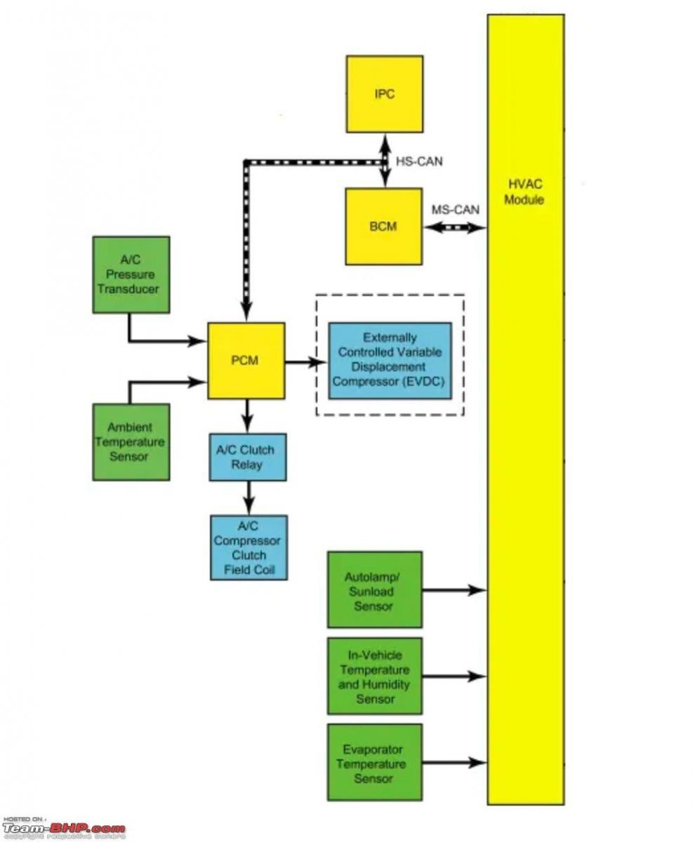 Ford Fiesta AC system functional diagram
These systems utilize various sensors to monitor temperature, pressure, and even sunlight, adjusting the AC operation accordingly.
Types of Car AC Compressors: Clutch vs. Variable Displacement
There are primarily two main types of car AC compressors: clutch-type and variable displacement. Some systems also employ a combination of both.
-
Clutch-Type Compressors: These are typically found in older vehicles. They operate on an on/off principle, engaging and disengaging using an electromagnetic clutch. When cooling is needed, the clutch engages, connecting the compressor to the engine’s belt drive and activating it. You can often hear a distinct “click” when the clutch engages. These systems cycle on and off to maintain the desired temperature.
-
Variable Displacement Compressors: Modern vehicles often use variable displacement compressors. Unlike clutch-type compressors, these run continuously once the engine is started. However, they regulate the amount of refrigerant they pump based on cooling demand. This is achieved through an internal control mechanism that adjusts the compressor’s displacement volume. While offering more consistent cooling, a drawback is that they operate even when AC isn’t actively needed, leading to slight engine drag and wear.
-
Clutch-Variable Compressors: Combining the benefits of both, some compressors use a clutch-variable system. This allows the compressor to disengage completely when AC is not required, reducing unnecessary wear and power consumption, while still offering variable displacement for efficient cooling when needed.
The compressor we disassembled from the Ford Fiesta is a clutch-variable type, representing a common design in modern vehicles.
Disassembling the AC Compressor: A Step-by-Step Exploration
Now, let’s delve into the disassembly process of the AC compressor. Our aim was not repair, but exploration and understanding, with the long-term goal of creating a “cut-away” display model to showcase the internal components – a cool addition to any garage!
Here’s the compressor we’re working with, both the old unit removed from the Fiesta and the new replacement:
The black pulley at the front houses the electromagnetic clutch. The electrical connector visible is for activating the clutch. Another connector on top of the housing is for the control valve of the variable displacement mechanism.
Before working on any AC system component, it’s crucial to understand if the replacement part is pre-filled with oil. AC systems require a precise amount of lubrication oil. During a system recharge, refrigerant with the correct oil quantity and a leak-detecting dye is added. Workshop manuals specify the oil capacity for the entire system and individual components.
Checking the compressor’s model plate is always recommended. This compressor, an original Ford part manufactured in Hungary in 2015, uses R134A refrigerant, a common type in automotive AC systems.
Let’s focus on the clutch mechanism. Here’s a closer look:
The electrical lead powers the electromagnet that engages the clutch.
To remove the pulley and clutch, a small bolt on the shaft needs to be unscrewed. Holding the pulley securely in a vise allowed for easy removal of this bolt.
This image shows the inner side of the clutch plate. When the electromagnet is activated, it pulls this plate towards the pulley, engaging the clutch. Note the bearing in the center of the pulley, allowing it to freewheel when the clutch is disengaged. The splines on the clutch plate center engage with corresponding splines on the compressor shaft, directly linking the clutch to the compressor’s rotation.
The clutch plate assembly consists of the main plate, a spring, and a smaller plate. The spring ensures the clutch disengages when the electromagnet is deactivated. The gap between the clutch plate and pulley can indicate clutch wear. Replacing the bearing or the entire clutch is a common repair, often achievable without removing the compressor or discharging the refrigerant. For instance, clutch bearing replacement on a Jeep AC system is a task that can be done relatively easily.
This image shows the sequence of components removed: bolt and washer, clutch plate, circlip (for bearing lock), pulley with bearing, and the exposed electromagnet. Bearings and clutches are common wear points in AC compressors, as the pulley spins whenever the engine is running.
The electromagnet features green felt, likely acting as a seal against dirt and debris from the clutch mechanism.
Removing the electromagnet reveals green dye on the clutch sprocket – a clear sign of a refrigerant leak!
This “green gunk” is a mixture of lubrication oil and the leak-detecting dye. Compressor leaks often occur at pipe connections (easily fixed with O-ring replacement) or, more commonly, at the front seal of the compressor shaft, as seen in this case. The dye, visible under UV light, helped pinpoint the front seal as the leak source. The splines on the shaft are evident, matching those on the clutch plate for direct engagement.
Deeper inside the recess, another bearing and circlip are visible. While theoretically replaceable, these internal components often require specialized tools and expertise. In many regions, replacing the entire compressor is often more cost-effective than attempting to repair a front seal leak due to labor costs and the potential for recurring leaks. While front seal leaks aren’t typical for these Ford compressors, our Fiesta, with 97,000 kilometers, unfortunately developed this issue. The felt around the bearing/seal likely provides additional protection against contamination.
Further disassembly involves separating the compressor body. It comprises three main sections: the front assembly we’ve been working on, the middle section containing the cylinders, and the rear section housing the control solenoid and valve plates.
Conclusion
Disassembling the car AC compressor provided a valuable hands-on learning experience, revealing the intricate components within this vital automotive system part. Understanding the car ac parts diagram, the function of each component, and the different types of compressors enhances your ability to diagnose AC issues and appreciate the engineering behind automotive comfort systems. While component-level repair of compressors can be complex, knowing the basics empowers car owners and enthusiasts to make informed decisions regarding AC maintenance and repair.
For more detailed information and continued exploration of car AC compressors and systems, refer back to BHPian Jeroen’s thread on car AC compressors. This and similar resources offer a wealth of knowledge for anyone wanting to deepen their understanding of automotive technology.