Recently, BHPian Jeroen, a fellow car enthusiast, shared his experience of dismantling a car AC compressor. Inspired by his hands-on approach, we decided to delve deeper into the anatomy of these crucial components. As experts in car repair at carparteu.com, we aim to provide an enhanced guide, optimized for our English-speaking audience, focusing on “Car Air Compressor Parts” and their function within the vehicle’s air conditioning system.
Drawing from Jeroen’s insightful exploration and our expertise, this article will dissect a typical car air compressor, revealing its internal workings and key parts. Whether you’re a seasoned mechanic or a curious car owner, understanding these components is essential for maintenance and repair.
Before we get our hands greasy, let’s briefly touch upon how a car AC system operates. This knowledge is fundamental to appreciate the role of each car air compressor part.
Diagram illustrating the basic components of a car air conditioning system, including the compressor, condenser, evaporator, and expansion valve.
As shown in the diagram, the compressor is the heart of the system. Its primary function is to compress the refrigerant, increasing its pressure and temperature before it circulates through the rest of the system. The high-pressure refrigerant then moves to the condenser, where it dissipates heat and turns into a liquid. This liquid refrigerant flows through the expansion valve, which reduces its pressure and temperature drastically, before entering the evaporator. The evaporator, typically located inside the car’s dashboard, absorbs heat from the cabin air, cooling it down. Finally, the low-pressure refrigerant returns to the compressor to repeat the cycle.
Modern car AC systems are sophisticated, incorporating various sensors and control units to optimize performance and efficiency. These systems monitor internal and external temperatures, sun load, and refrigerant pressures to regulate the AC operation.
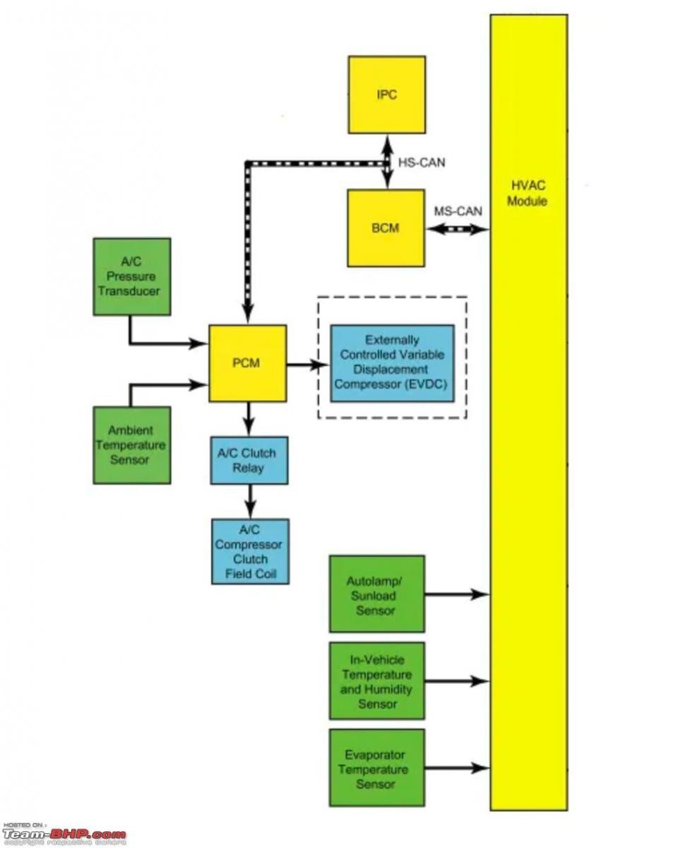 Functional diagram of a Ford Fiesta AC system
Functional schematic of a Ford Fiesta car air conditioning system, highlighting the integration of sensors and control mechanisms for system regulation.
Car air compressors come in different designs, primarily distinguished by their clutch mechanisms: clutch-only, variable displacement, or a combination of both. Older vehicles often utilize clutch-only systems, which operate on an on/off principle, engaging and disengaging based on system pressure. In contrast, variable displacement compressors are designed to run continuously, adjusting their refrigerant pumping volume to meet cooling demands. Modern vehicles frequently employ clutch-variable compressors, aiming to balance efficiency and longevity.
Variable compressors, while offering precise cooling control, can present challenges. Continuous operation, even when AC is not actively needed, leads to wear and engine load, slightly impacting fuel economy. Furthermore, lack of use in some variable compressor designs can lead to lubrication issues, especially if refrigerant levels are low, as the refrigerant also carries the lubricating oil. This is why clutch-variable compressors have become increasingly prevalent, offering a more refined approach to AC system management.
Now, let’s get to the exciting part – dissecting a car air compressor to understand its internal car air compressor parts. We’ll be examining a compressor similar to the one Jeroen worked on, giving you a visual and detailed breakdown.
Comparison view of an old, removed car AC compressor and a new replacement compressor, emphasizing the visual differences and condition.
Before starting any work on your car AC system or its parts, it’s crucial to know whether the replacement compressor comes pre-filled with oil. AC systems require a specific amount of lubrication oil, and incorrect levels can harm performance and longevity. When recharging the system after component replacement, refrigerant with the correct oil quantity and a leak-detecting dye is added. Always consult your vehicle’s workshop manual for precise oil and refrigerant specifications. The manual typically outlines the oil capacity for the entire system and individual car air compressor parts like the compressor, dryer, and evaporator.
Detailed view of a car AC compressor’s model plate, showing manufacturer details, model number, refrigerant type (R134A), and manufacturing origin.
Always inspect the compressor’s model plate for vital information like the refrigerant type and manufacturer details. The compressor in our example uses R134A refrigerant, a common standard in modern vehicles.
Disassembling the Clutch and Pulley System
The clutch and pulley assembly is located at the front of the compressor. This mechanism engages and disengages the compressor based on the AC system’s demand.
Focused image of the car AC compressor clutch assembly, clearly showing the pulley, clutch plate, and electrical connector for the electromagnet.
The electrical connector visible in the image powers an electromagnet, which is responsible for engaging the clutch.
Image highlighting the electrical connector leading to the electromagnet of the car AC compressor clutch, responsible for clutch engagement.
To remove the pulley and clutch, start by detaching the small bolt on the compressor shaft. A vise may be needed to secure the pulley while loosening the bolt.
Action shot of removing the central bolt from the car AC compressor shaft, which secures the clutch assembly and pulley.
Examining the clutch plate reveals its internal structure. When the electromagnet is activated, it pulls the clutch plate towards the pulley, engaging the compressor. Note the bearing at the center of the pulley, allowing it to freewheel when the clutch is disengaged and the compressor is idle. The clutch plate’s splined center mates with corresponding splines on the compressor shaft, creating a direct connection upon engagement.
Internal view of the car AC compressor clutch plate, showcasing the splined center and spring mechanism, which are crucial for engagement and disengagement.
The clutch plate assembly consists of the clutch plate itself, a spring, and a smaller backing plate. The electromagnet’s action overcomes the spring’s resistance to engage the clutch. The gap between the clutch plate and pulley can indicate clutch wear.
Component view of the disassembled car AC compressor clutch parts, arranged in order of removal, including the bolt, clutch plate, circlip, pulley with bearing, and electromagnet.
Common wear items in these car air compressor parts are the bearing and clutch. Even when the AC is off, the pulley continues to spin, potentially leading to bearing wear. Replacing the bearing or clutch is often straightforward and can be done without removing the compressor or discharging the refrigerant, saving time and cost.
Ordered display of disassembled car AC compressor clutch parts, emphasizing each component and its role in the clutch mechanism.
A close-up of the electromagnet reveals a green felt seal, likely designed to protect against dirt and debris from the clutch mechanism.
Detailed image of the car AC compressor electromagnet, highlighting the green felt seal which acts as a barrier against contaminants.
With the electromagnet removed, we can see green dye residue on the clutch sprocket – a clear indication of a refrigerant leak.
Front view of the disassembled car AC compressor assembly, showing green dye residue indicative of a refrigerant leak, particularly around the shaft seal.
This compressor likely failed due to a front seal leak, a common issue in car air compressor parts. Leaks can also occur at pipe connections, but shaft seal leaks are frequent. The dye helps pinpoint leak locations, and in this case, it’s concentrated around the compressor shaft.
Close inspection of the car AC compressor shaft splines and front seal area, revealing the complexity of the sealing system and potential leak points.
Inside the compressor front assembly, another bearing and circlip are visible, further securing the shaft. While theoretically replaceable, these parts often require specialized tools and expertise. In many regions, due to labor costs and part availability, replacing the entire compressor is often more practical and cost-effective than attempting seal replacements.
Image showing the initial separation of the car AC compressor body, revealing the internal components like cylinders and valve plates.
Removing more circlips allows for separating the compressor body into sections. Typically, a compressor body is divided into three main parts: the front assembly, the central section containing cylinders, and the rear section housing the control solenoid and valve plates.
View of the car AC compressor body partially disassembled, showing the separation into distinct sections and hinting at the internal mechanical complexity.
Conclusion
Disassembling a car AC compressor reveals the intricate engineering within these vital car air compressor parts. From the clutch and pulley system to the internal cylinders and valves, each component plays a crucial role in the cooling process. Understanding these parts not only satisfies curiosity but also empowers car owners and mechanics to diagnose issues and perform maintenance effectively. While component-level repair of compressors can be complex, recognizing common failure points like seals, bearings, and clutches can guide informed decisions about repair or replacement.
For a more in-depth exploration and visual journey into car AC compressor anatomy, we highly recommend visiting BHPian Jeroen’s detailed thread on car AC compressors. His firsthand experience and detailed photographs provide further valuable insights into these essential automotive components.