Like many, I’ve always driven cars without truly grasping what’s happening under the hood. Beyond basic maintenance like air filter replacements or oil changes, car mechanics remained a mystery. When faced with car troubles, mechanic explanations often felt like a foreign language. But recently, a desire to understand the inner workings of my vehicle sparked. Not to become a professional mechanic, but to gain a fundamental knowledge of how a car operates. This understanding will not only help decipher mechanic jargon but also empower me with practical knowledge about everyday technology. Just as I understand the mechanics of website coding and SEO, it’s time to explore the tangible mechanics of my car.
I suspect many men share this curiosity – a desire to understand the machines we rely on daily. Thus begins “Gearhead 101,” a series dedicated to explaining the basics of car mechanics. Our first lesson delves into the heart of your car: the internal combustion engine. We’ll explore its components using a Car Engine Diagram Parts approach and explain how they work together.
What is an Internal Combustion Engine?
The term “internal combustion engine” signifies that fuel and air combustion occurs within the engine itself. This combustion generates energy, moving pistons and ultimately propelling your car.
This differs from external combustion engines, like steam engines, where fuel burns outside the engine. In steam engines, external burning heats water to create steam, which then powers the engine.
Interestingly, internal combustion engines predate practical steam engines. While ancient Greeks experimented with steam power, the first functional engines utilized gunpowder for internal combustion in the 16th century. These early engines, known as atmospheric engines, were inefficient, relying on vacuum creation after gunpowder explosions to move pistons. By the 17th century, steam engines gained prominence, overshadowing internal combustion concepts.
It wasn’t until 1860 that Jean Joseph Etienne Lenoir, a Belgian inventor, patented a reliable internal combustion engine. Lenoir’s engine injected natural gas into a cylinder, igniting it with a nearby flame. While functional, it was still inefficient.
Building upon Lenoir’s work, German engineers Nicolaus August Otto and Eugen Langen founded an engine company in 1864. Otto later developed a more efficient design, the four-stroke engine, which remains the foundation of modern car engines.
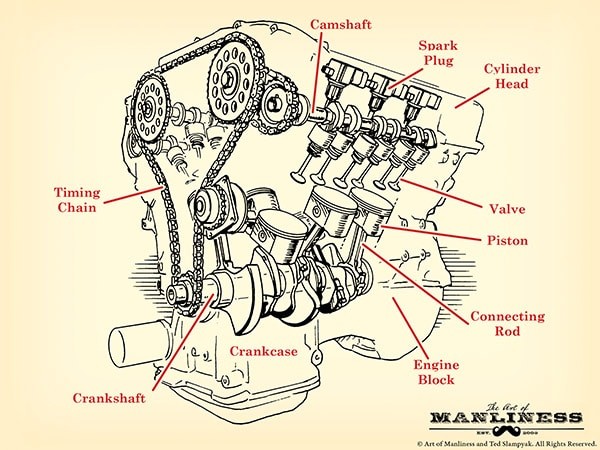
Exploring the Anatomy: Car Engine Diagram Parts
Before diving into the four-stroke engine cycle, let’s familiarize ourselves with the key car engine diagram parts. Understanding these components will clarify their roles in the engine’s operation. Some terms may seem confusing initially, but a comprehensive overview will solidify your understanding.
1. Engine Block (Cylinder Block):
The engine block is the structural core of the engine. Typically made from aluminum alloy or iron, it’s also called the cylinder block due to the integrated cylinders – hollow tubes where pistons move. More cylinders generally equate to greater engine power. The block also contains channels for oil and coolant circulation.
V6 and V8 Engine Configurations:
These designations refer to the cylinder arrangement. Inline engines have cylinders in a straight line. Flat-four engines have horizontally opposed cylinders. Engines with more than four cylinders often use a V-configuration, dividing cylinders into two banks. A V6 engine has six cylinders in a V-shape, and a V8 engine has eight.
2. Combustion Chamber:
This is where the power generation happens. Fuel, air, pressure, and spark combine to create controlled explosions that drive the pistons. The combustion chamber is formed by the cylinder walls, the piston top (floor), and the cylinder head (ceiling).
3. Cylinder Head:
The cylinder head sits atop the engine cylinders, sealing the combustion chamber. It features indentations for combustion space and mounts components like intake/exhaust valves, spark plugs, and fuel injectors. A head gasket ensures a tight seal between the cylinder head and block.
4. Piston:
Pistons are inverted cup-shaped components moving vertically within the cylinders. Combustion force pushes them down, rotating the crankshaft. They connect to the crankshaft via connecting rods and piston pins. Piston rings, located in grooves on the piston’s top, seal against the cylinder walls. Compression rings (top rings) ensure combustion chamber sealing, while oil rings (bottom rings) prevent oil leakage into the chamber and manage cylinder wall lubrication.
5. Crankshaft:
The crankshaft converts the linear piston motion into rotational motion, powering the car’s drivetrain. It runs lengthwise within the engine block. At the front, it connects to belts driving components like the camshaft. At the rear, it links to the drivetrain, transferring power to the wheels. Oil seals (O-rings) prevent leaks at crankshaft ends.
The crankshaft resides in the crankcase, located below the cylinder block, protecting it and connecting rods. The lower crankcase area is the oil pan, storing engine oil. An oil pump circulates oil through a filter, lubricating crankshaft bearings, connecting rods, and cylinder walls before returning to the oil pan. Balancing lobes on the crankshaft counteract wobbling during rotation. Main bearings provide smooth crankshaft rotation within the engine block.
6. Camshaft:
Often referred to as the engine’s “brain,” the camshaft precisely controls valve timing in coordination with the crankshaft via a timing belt or chain. Egg-shaped lobes along the camshaft dictate valve opening and closing. Inline engines typically have a single camshaft, while V-shaped engines often use two (one per cylinder bank), or even four (two per bank) for enhanced valve control.
7. Timing System:
The timing belt or chain synchronizes crankshaft and camshaft rotation, maintaining precise valve timing. If synchronization is lost, the engine will malfunction.
8. Valvetrain:
This system, mounted on the cylinder head, operates the engine valves and includes valves, rocker arms, pushrods, and lifters.
9. Valves:
Intake valves allow air-fuel mixture into the combustion chamber, while exhaust valves expel combustion gases. Most cars have one intake and one exhaust valve per cylinder. Performance cars often use multi-valve systems (four valves per cylinder – two intake, two exhaust) for improved engine “breathing” and performance.
10. Rocker Arms:
These levers interact with camshaft lobes. As a lobe lifts one end of the rocker arm, the other end presses down on the valve stem, opening the valve.
11. Pushrods/Lifters:
In overhead valve engines, where camshaft lobes don’t directly contact rocker arms, pushrods or lifters transmit motion from the camshaft to the rocker arms.
12. Fuel Injectors:
Modern cars use fuel injection systems to deliver fuel to the combustion chamber, replacing older carburetors. Direct fuel injection injects fuel directly into each cylinder. Ported fuel injection sprays fuel into the intake manifold near the valves. Throttle body injection uses a single injector in the throttle body to mix fuel and air before distribution to cylinders.
13. Spark Plug:
Located above each cylinder, the spark plug ignites the compressed air-fuel mixture, initiating combustion and pushing the piston down.
The Four-Stroke Cycle: Powering Your Vehicle
Now, understanding the car engine diagram parts, let’s examine the four-stroke cycle, the sequence that drives your car. This cycle occurs in each cylinder, repeated thousands of times per minute.
- Intake Stroke: The piston moves down, drawing air-fuel mixture into the cylinder through the open intake valve.
- Compression Stroke: The intake valve closes, and the piston moves up, compressing the air-fuel mixture.
- Combustion Stroke (Power Stroke): The spark plug ignites the compressed mixture, causing a powerful explosion that forces the piston down.
- Exhaust Stroke: The exhaust valve opens, and the piston moves up, pushing exhaust gases out of the cylinder.
This continuous four-stroke cycle in each cylinder generates the power that moves your car.
This overview provides a foundational understanding of car engines. Take a look under your car’s hood and try to identify these car engine diagram parts. For deeper learning, explore resources like “How Cars Work” by Tom Newton, which offers further insights into automotive mechanics.