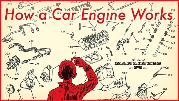
Have you ever looked under the hood of your car and been overwhelmed by the maze of belts, hoses, and metal parts? For many, the car engine remains a mystery, a powerful black box that somehow makes our vehicles move. But understanding the basics of your car’s engine isn’t as daunting as it seems. In this guide, we’ll break down the anatomy of a car engine using a Car Motor Parts Diagram, explaining each component and its role in the fascinating process of internal combustion. Whether you’re a budding mechanic or simply curious about what makes your car tick, this overview will provide you with a solid foundation.
A Brief History of the Internal Combustion Engine
Before diving into the car motor parts diagram, it’s helpful to appreciate the journey of the internal combustion engine. Contrary to popular belief, internal combustion predates the steam engine in concept. Early iterations appeared as far back as the 16th century, utilizing gunpowder to drive pistons. These were inefficient “atmospheric engines” that relied on vacuum pressure after an explosion.
Steam engines, burning fuel externally to heat water and generate power, gained prominence in the 17th century, overshadowing early internal combustion efforts. However, the quest for a more efficient engine continued. In 1860, Jean Joseph Etienne Lenoir patented a working internal combustion engine, using natural gas ignited by a flame.
Building upon Lenoir’s work, Nicolaus August Otto, in 1876, revolutionized engine technology by developing the four-stroke engine. Otto’s design, still the foundation of modern car engines, marked a significant leap in efficiency and reliability. Understanding this history provides context for the sophisticated machinery under your car’s hood today.
Exploring the Car Engine: Component by Component with Diagrams
To truly grasp how a car engine operates, let’s dissect its key components. The following sections will guide you through a detailed car motor parts diagram and explain the function of each part.
1. Engine Block (Cylinder Block)
The engine block, also known as the cylinder block, is the core structure of the engine. Typically cast from aluminum alloy or iron, it houses the cylinders – hollow tubes where pistons move. The number of cylinders often dictates engine power; more cylinders generally mean more power. Beyond cylinders, the block contains intricate channels for oil and coolant circulation, essential for engine lubrication and temperature regulation.
V6 vs. V8 Engine Configurations: Reading the Diagram
Engine configurations like V6 or V8, often seen in car motor parts diagrams, refer to the arrangement and number of cylinders. Inline engines have cylinders arranged in a straight line. Flat engines (like “flat-four”) lay cylinders horizontally. When engines have more than four cylinders, they’re usually in a “V” configuration, split into two banks. A V6 engine has six cylinders in a V shape (three per bank), and a V8 has eight (four per bank), clearly visualized in a car engine diagram.
2. Combustion Chamber
The combustion chamber is where the power of the engine is generated. It’s the space where fuel and air mix, compress, and ignite, causing an explosion that drives the pistons. As you can see in a car parts diagram, the combustion chamber is formed by the cylinder walls, the top of the piston (as the floor), and the cylinder head (as the ceiling).
3. Cylinder Head
Positioned atop the engine cylinders, the cylinder head is a crucial component detailed in any comprehensive car motor parts diagram. It’s crafted with indentations forming part of the combustion chamber. A head gasket seals the joint between the cylinder head and block, preventing leaks. The cylinder head also serves as the mounting point for intake and exhaust valves, spark plugs, and fuel injectors, all vital components for the combustion process.
4. Piston
Pistons are cylindrical components that move up and down within the cylinders. A car engine parts diagram will show pistons connected to the crankshaft via connecting rods. The force from combustion pushes the piston down, which, in turn, rotates the crankshaft. Piston rings, located in grooves on the piston’s top, seal the combustion chamber and regulate oil on the cylinder walls. Compression rings create a tight seal for combustion, while oil rings prevent oil leakage into the chamber.
5. Crankshaft
The crankshaft is a rotating shaft that converts the linear motion of the pistons into rotational motion, the driving force of the car. As depicted in a car motor parts diagram, it sits at the bottom of the engine block in the crankcase. The crankshaft connects to the camshaft via belts or chains and to the drivetrain, which ultimately powers the wheels. Oil seals prevent oil leaks, and main bearings ensure smooth rotation within the engine block. Balancing lobes (counterweights) on the crankshaft minimize vibrations during rotation.
6. Camshaft
Often referred to as the “brain” of the engine, the camshaft, shown in a car engine diagram, works in sync with the crankshaft via a timing belt or chain. It controls the precise timing of valve opening and closing for optimal engine performance. Lobes along the camshaft dictate valve operation. Inline engines typically use a single camshaft, while V-shaped engines may have one or two per cylinder bank, depending on valve arrangement.
7. Timing System
The timing system, involving the timing belt or chain, is crucial for synchronizing the crankshaft and camshaft. A car parts diagram will illustrate the connection between these components. This synchronization ensures valves open and close at the correct moments in relation to piston movement. If timing is off, the engine won’t run.
8. Valvetrain
The valvetrain, mounted on the cylinder head and visible in a detailed car motor parts diagram, manages the valves. It includes valves, rocker arms, pushrods, and lifters.
9. Valves: Intake and Exhaust
Valves are critical for controlling the flow of gases into and out of the combustion chamber. Intake valves allow the air-fuel mixture to enter, while exhaust valves let combustion gases escape. Most engines have at least one intake and one exhaust valve per cylinder. High-performance engines often employ multiple valves per cylinder (e.g., two intake and two exhaust) to improve engine “breathing” and power output, as highlighted in advanced car engine diagrams.
10. Rocker Arms
Rocker arms are levers that interact with the camshaft lobes. As the camshaft rotates, the lobes push on the rocker arms, which then open and close the valves. This see-saw action is a key part of the valvetrain mechanism, demonstrable in a car motor parts diagram.
11. Pushrods and Lifters
In engines with overhead valves, pushrods and lifters transmit motion from the camshaft to the rocker arms. When camshaft lobes don’t directly contact rocker arms, these intermediary parts are necessary to actuate the valves, as shown in certain engine parts diagrams.
12. Fuel Injectors
Fuel injectors are responsible for delivering fuel to the combustion chamber. Modern cars use fuel injection systems instead of carburetors. Direct fuel injection sprays fuel directly into the cylinder. Ported fuel injection sprays fuel into the intake manifold, just outside the intake valve. Throttle body fuel injection, a less common system, uses a single injector in the throttle body. A car engine diagram may illustrate the location of fuel injectors relative to the cylinders and intake system.
13. Spark Plugs
Spark plugs, positioned above each cylinder, ignite the air-fuel mixture in the combustion chamber. The spark initiates the controlled explosion that drives the piston down, initiating the engine’s power cycle. Spark plug location is clearly indicated in a car motor parts diagram.
The Four-Stroke Cycle: Powering Your Vehicle
Understanding the four-stroke cycle is essential to understanding how all these parts work together to move your car. As illustrated in a four-stroke engine diagram, the cycle consists of four distinct strokes of the piston:
- Intake Stroke: The piston moves down, drawing a mixture of air and fuel into the cylinder through the open intake valve.
- Compression Stroke: The intake valve closes, and the piston moves up, compressing the air-fuel mixture.
- Combustion Stroke (Power Stroke): The spark plug ignites the compressed mixture. The resulting explosion forces the piston down, generating power.
- Exhaust Stroke: The exhaust valve opens, and the piston moves up, pushing the exhaust gases out of the cylinder.
This four-stroke cycle repeats continuously in each cylinder, thousands of times per minute, creating the power that propels your car.
Conclusion: From Diagram to Driving
By examining a car motor parts diagram and understanding the function of each component, the inner workings of a car engine become much clearer. From the engine block to the spark plugs, each part plays a vital role in the intricate dance of internal combustion. While this is a foundational overview, further exploration into specific engine types and systems will deepen your understanding. So, take a look under your car’s hood with newfound knowledge, and perhaps a car motor parts diagram in hand, to appreciate the engineering marvel that powers your daily drives.

