Have you ever looked under the hood of your car and felt completely lost? Most of us rely on our vehicles daily but understanding what makes them go can feel like a mystery. You’re not alone if the inner workings of a car engine seem complicated. Many people, even car owners, lack a basic understanding of these essential machines. This guide aims to change that. We’ll break down the anatomy of a car engine, exploring the function of each key component with the help of a Diagram Of Car Engine Parts. No need to be a “car guy” to grasp these fundamentals. Whether you want to better communicate with your mechanic or simply satisfy your curiosity about the technology you use every day, understanding your car engine is empowering.
Let’s start our journey into the world of engines by understanding the heart of it all: the internal combustion engine.
The Internal Combustion Engine Explained
The term “internal combustion engine” might sound technical, but the concept is quite straightforward. It’s an engine where fuel and air are combusted inside the engine itself. This combustion creates energy that moves pistons, ultimately powering your car.
This is different from an “external combustion engine,” like a steam engine. In those, fuel is burned outside the engine to heat water and create steam, which then drives the engine.
Interestingly, while steam engines might seem like an older technology, the internal combustion engine actually predates reliable steam-powered engines. Early versions in the 16th century used gunpowder! These weren’t very efficient. Gunpowder was ignited beneath a piston in a cylinder, creating a vacuum after the explosion that pulled the piston down. Because they relied on air pressure changes, they were called atmospheric engines. Steam engines became more promising in the 17th century, and internal combustion engine development slowed for a while.
It wasn’t until 1860 that a practical internal combustion engine emerged, thanks to Jean Joseph Etienne Lenoir. He patented an engine that used natural gas ignited by a flame. While an improvement, it still wasn’t very efficient.
Building on Lenoir’s work, Nicolaus August Otto and Eugen Langen, two German engineers, developed engines based on Lenoir’s design in 1864. Otto then went on to invent the four-stroke engine in 1876. This design was revolutionary, and its basic principles are still used in car engines today.
Exploring the Anatomy: Diagram of Car Engine Parts
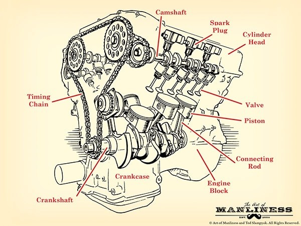
Diagram of car engine parts, illustrating a V8 engine layout and key components such as the engine block, cylinder head, pistons, crankshaft, camshaft, valves, and spark plugs.
Before we dive into the four-stroke cycle, let’s familiarize ourselves with the essential components using a diagram of car engine parts. Understanding each part’s role will make grasping the engine’s operation much easier. Some terms might seem confusing at first, but don’t worry. Read through the descriptions to get a general idea, and then revisit them for a deeper understanding of each component’s function.
Engine Block (Cylinder Block)
Think of the engine block as the engine’s skeleton. It’s the main structure, typically made from aluminum alloy or cast iron. You might also hear it called the cylinder block because it contains the cylinders – the hollow tubes where the pistons move up and down. More cylinders generally mean a more powerful engine. The engine block also houses channels for oil and coolant to circulate, keeping the engine lubricated and at the right temperature.
What do “V6” and “V8” mean?
These terms describe the engine’s cylinder arrangement and number. Four-cylinder engines often have cylinders in a straight line above the crankshaft – an inline engine.
Another four-cylinder configuration is the “flat four,” where cylinders are horizontally opposed in two banks with the crankshaft in the middle.
Engines with more than four cylinders often use a “V” configuration. Cylinders are split into two banks, angled like a “V”. A V-shaped engine with six cylinders is a V6; with eight cylinders, it’s a V8 (four cylinders per bank).
Combustion Chamber
This is where the action happens! The combustion chamber is where fuel, air, pressure, and a spark combine to create the explosion that drives the pistons. It’s formed by the cylinder walls, the top of the piston (acting as the floor), and the cylinder head (the ceiling).
Cylinder Head
The cylinder head is a metal component that sits above the engine cylinders, sealing them. It has indentations to create space for combustion at the top of the chamber. A head gasket ensures a tight seal between the cylinder head and engine block. Importantly, the cylinder head also houses intake and exhaust valves, spark plugs, and fuel injectors.
Piston
Pistons are like upside-down cans that move up and down within the cylinders. The force from combustion pushes the piston down, which in turn rotates the crankshaft. Each piston is connected to the crankshaft by a connecting rod (or con rod) and a piston pin. The connecting rod attaches to the crankshaft via a connecting rod bearing.
Around the top of each piston are grooves holding piston rings. These rings, made of iron, press against the cylinder walls to create a tight seal for the combustion chamber. There are typically two types: compression rings (top rings for sealing) and oil rings (bottom rings to prevent oil from entering the combustion chamber and to scrape excess oil back into the crankcase).
Crankshaft
The crankshaft is the component that transforms the piston’s up-and-down motion into the rotational motion that powers your car’s wheels. It sits lengthwise in the engine block, usually near the bottom. At the front, belts connect the crankshaft to the camshaft and other components. At the rear, it connects to the drivetrain, sending power to the wheels. Oil seals (O-rings) at each end prevent oil leaks.
The crankshaft resides in the crankcase, located beneath the cylinder block. The crankcase protects the crankshaft and connecting rods. The lower part of the crankcase is the oil pan, which stores the engine oil. An oil pump in the oil pan circulates oil through a filter and then to the crankshaft, connecting rod bearings, and cylinder walls for lubrication before it drains back into the oil pan to repeat the cycle.
Balancing lobes along the crankshaft act as counterweights to minimize wobbling during rotation, preventing engine damage. Main bearings provide smooth surfaces between the crankshaft and engine block for frictionless spinning.
Camshaft
Often called the “brain” of the engine, the camshaft works with the crankshaft via a timing belt or chain to precisely control the opening and closing of intake and exhaust valves for optimal engine performance. Egg-shaped lobes along the camshaft dictate valve timing.
Camshafts usually run through the upper engine block, above the crankshaft. Inline engines often use a single camshaft for both intake and exhaust valves. V-shaped engines may have two camshafts (one per cylinder bank) or even four (two per bank), depending on the valve arrangement.
Timing System
As mentioned, a timing belt or chain synchronizes the crankshaft and camshaft. This timing is crucial; it keeps them in the correct relative position throughout engine operation. If the timing is off (e.g., the timing chain skips), the engine won’t run properly.
Valvetrain
The valvetrain is the mechanical system mounted on the cylinder head that operates the valves. It includes valves, rocker arms, pushrods, and lifters.
Valves
There are two types of valves: intake and exhaust. Intake valves allow the air-fuel mixture into the combustion chamber. Exhaust valves let combustion gases out.
Cars typically have one intake and one exhaust valve per cylinder. High-performance engines may have four valves per cylinder (two intake, two exhaust) for improved “breathing” and performance. Some engines even use three valves per cylinder (two intake, one exhaust).
Rocker Arms
Rocker arms are levers that interact with the camshaft lobes. As a lobe pushes on one end of the rocker arm, the other end presses down on the valve stem, opening the valve. It’s a see-saw-like action.
Pushrods/Lifters
In overhead valve engines, where the camshaft isn’t directly above the valves, pushrods or lifters transfer motion from the camshaft lobes to the rocker arms. In overhead camshaft engines, the lobes often act directly on the rocker arms.
Fuel Injectors
Fuel is essential for combustion. Before the 1980s, carburetors were used to supply fuel. Modern cars use fuel injection systems, which are more efficient. Common types include:
- Direct Fuel Injection: Each cylinder has an injector that sprays fuel directly into the combustion chamber at the optimal moment.
- Ported Fuel Injection: Fuel is sprayed into the intake manifold, just outside the intake valve. When the valve opens, air and fuel enter the cylinder.
- Throttle Body Fuel Injection: A single injector feeds fuel into a throttle body where it mixes with air and is then distributed to the cylinders via the intake valves (similar in concept to carburetors).
Spark Plug
Located above each cylinder, the spark plug ignites the compressed air-fuel mixture with a spark. This ignition causes the rapid expansion of gases – the mini-explosion – that pushes the piston down.
The Four-Stroke Cycle: Powering Your Vehicle
Diagram of a four-stroke engine cycle, illustrating the intake, compression, combustion (power), and exhaust strokes with piston and valve movements.
Now that we know the parts, let’s see how they work together in the four-stroke cycle, illustrated in the diagram of car engine parts above. This cycle, happening in each cylinder, is what makes your car move. Imagine this cycle repeating thousands of times per minute, and you’ll understand how your car generates power.
- Intake Stroke: The piston moves down, drawing a mixture of air and fuel into the cylinder through the open intake valve. The exhaust valve is closed.
- Compression Stroke: Both intake and exhaust valves close. The piston moves upward, compressing the air-fuel mixture. This compression increases the mixture’s temperature and readies it for combustion.
- Combustion (Power) Stroke: At the peak of compression, the spark plug fires, igniting the air-fuel mixture. The resulting explosion forces the piston powerfully downwards. This is the stroke that generates the engine’s power.
- Exhaust Stroke: The exhaust valve opens, and the piston moves upward again, pushing the burnt gases out of the cylinder through the exhaust valve. The intake valve remains closed.
This four-stroke cycle repeats continuously in each cylinder, converting fuel into motion and driving your car.
And there you have it – the basics of how a car engine works! Take some time to look under the hood of your car and see if you can identify some of these parts. To delve deeper, consider exploring resources like “How Cars Work” by Tom Newton, which provides even more detail in an accessible way. Understanding your engine is the first step to appreciating the marvel of engineering that gets you where you need to go every day.