Experiencing speedometer visibility issues, especially when sunlight glares off your dashboard? Many drivers face this frustrating and potentially dangerous problem. On carpartseu.com, we understand these challenges, and we’re excited to present a solution: building your own Digital Speedometer Obd2 gauge. This project not only resolves the visibility issue but also offers a fantastic base for creating various custom OBD-II based gauges for your vehicle.
The Case for a Digital Speedometer OBD2 Solution
Let’s face it, sometimes car manufacturers drop the ball on crucial design elements. Take the traditional analog speedometer in my Mitsubishi Pajero for example. In bright sunlight, particularly common here in Saudi Arabia, reading the speedometer became a near-impossible task. This isn’t just an inconvenience; it’s a serious safety concern, especially in a region known for challenging driving conditions.
Driving in Saudi Arabia presents unique hazards. With alarming road fatality statistics, staying vigilant about speed is paramount. While efforts to improve road safety, like speed cameras, are in place, the importance of a clearly visible speedometer cannot be overstated. The stock speedometer in my Pajero, with its design flaws – black pointers, grey background, and shadowed numerals – made quick speed checks difficult, if not dangerous. This is where the idea for a digital speedometer OBD2 gauge was born.
Traditional solutions like Heads-Up Displays (HUDs) and smartphone-based speedometers have their drawbacks. HUDs can suffer from washed-out displays in sunlight and slow refresh rates. Smartphone solutions can be bulky and lack dedicated functionality. GPS-based speedometers, while convenient, are unreliable in tunnels or underpasses – locations where speed cameras might be present.
Therefore, a more robust and reliable solution is needed. Enter the DIY digital speedometer OBD2 gauge. By tapping into your car’s On-Board Diagnostics II (OBD-II) system, we can access real-time vehicle speed data and display it on a bright, easily readable screen. This project leverages the power of OBD-II, a standard interface in most cars built since 2008, to create a compact and efficient digital speedometer OBD2.
Harnessing the Power of OBD-II for Your Digital Speedometer
OBD-II is a standardized system that provides access to a wealth of vehicle data, from speed and RPM to engine temperature and more. Using inexpensive and readily available OBD-II interfaces, we can extract this data for our digital speedometer OBD2 project. These interfaces, often based on the ELM327 chip, communicate with your car’s computer and can be connected via USB or Bluetooth.
Figure 1: Common OBD-II modules – USB (left) and Bluetooth (right)
For this project, we’ll focus on a USB-based ELM327 interface due to its simplicity for hardware modification. The goal is to intercept the data stream from the OBD-II port and display the speed information on a small, bright OLED screen mounted in the driver’s line of sight. This digital speedometer OBD2 will provide instant, clear speed readings, eliminating the visibility issues of the stock speedometer.
The core of our digital speedometer OBD2 modification involves using a compact and powerful Atmel ATtiny85 microcontroller. This tiny chip will be integrated directly into the ELM327 USB module, along with a vibrant OLED display. A custom-designed 3D-printed enclosure will house the display, creating a clean and professional-looking digital speedometer OBD2 gauge that can be discreetly mounted on your dashboard.
Inside the OBD-II Interface: Modification for Digital Speedometer
To create our digital speedometer OBD2, we need to modify the internal workings of a standard ELM327 USB OBD-II interface. Typically, these modules contain three main components: a CAN bus interface chip, an ELM327 microcontroller, and a USB interface chip (like PL2303 or CH340). In their original configuration, data flows from the car’s CAN bus, through the ELM327, and out via USB to a computer.
Figure 2: Block diagram of ELM327 USB module BEFORE modification
Our modification reroutes the serial communication lines from the ELM327 microcontroller. Instead of going to the USB chip, these lines will connect to our ATtiny85 microcontroller. The USB chip becomes redundant in our digital speedometer OBD2 setup.
Figure 3: Block diagram of ELM327 USB module AFTER modification
While some online guides suggest slowing down the serial communication speed of the ELM327, this isn’t always feasible with newer, cost-effective clone processors. Our design embraces the faster 38,400bps serial speed, ensuring rapid data transfer and display updates for our digital speedometer OBD2. The ATtiny85 microcontroller, running at 16MHz, efficiently processes the data and drives the OLED display via the I2C bus. Only the necessary display pixels are updated, resulting in a smooth, flicker-free digital speedometer OBD2.
The 128×64 pixel OLED display offers excellent graphical capabilities. For optimal readability, we’ll use large, 40×32 pixel digits for the speed display. Units (kph or mph, selectable via a jumper) will be displayed in a slightly smaller font. The speed display will update approximately ten times per second, providing a highly responsive digital speedometer OBD2.
In addition to speed, our digital speedometer OBD2 will also incorporate an engine coolant temperature bar graph. This secondary display, updated less frequently (around every 30 seconds), provides valuable engine health information. The bar graph is designed with an expanded “normal” temperature range for better monitoring of typical operating temperatures.
Figure 4: Oil temperature bar graph scale
Circuit Schematic and Component Breakdown for Your Digital Speedometer OBD2
The schematic for our digital speedometer OBD2 modification is remarkably simple, utilizing a low component count.
Figure 5: Schematic details for ELM327 display modification
Power for the ATtiny85 and OLED display is drawn from the 5V regulator already present within the OBD-II USB interface. The interface’s built-in voltage spike protection safeguards our components. The ELM327’s RxD and TxD lines connect directly to the ATtiny85 for serial communication. The OLED display communicates with the ATtiny85 via a standard I2C interface (SDA and SCL lines). A jumper on the ATtiny85 allows switching between kph and mph units for your digital speedometer OBD2.
A key consideration is power management. The OBD-II port provides constant power, even when the ignition is off. To prevent battery drain, we incorporate a miniature toggle switch to manually control power to the digital speedometer OBD2 module. A spare pin on the ATtiny85 is reserved for potential future enhancements, such as automatic power on/off.
Parts You’ll Need to Build Your Digital Speedometer OBD2
Building this digital speedometer OBD2 is surprisingly affordable. Here’s a list of the required components:
Table 2: Parts list for the speedometer
The total cost for new components should be under $20. Many DIYers may already have some of these parts on hand, further reducing the cost of this digital speedometer OBD2 project.
Step-by-Step Construction Guide for Your Digital Speedometer OBD2
The prototype construction is straightforward. The ATtiny85, bypass capacitor, and LCD connector are assembled on a small prototyping board. A socket for the ATtiny85 is recommended for easy programming. A 4-pin connector provides a robust connection to the OLED display.
The ELM327 OBD-II USB interface needs to be carefully opened for modification. Remove the front panel and unscrew the enclosure. Detach the OBD-II connector and USB cable from the PCB, noting the orientation of the OBD-II connector.
The crucial modification step involves isolating the USB chip’s TxD pin. For PL2303 chips, carefully lift pin 1; for CH340G chips, lift pin 2.
Figure 6: Modification to pin 1 of the PL2303 USB chip in the ELM327 USB module
This prevents signal conflicts. Next, drill a hole in the enclosure for the toggle switch and wire it into the +12V supply line as shown:
Figure 7: Modification to switch the +12V supply in the ELM327 USB module
Solder wires for +5V, ground, RxD, and TxD from the ELM327 PCB to the ATtiny85 board, following Figures 8 and 9 for connection points.
Figure 8: Adding RxD (Green), TxD (White) and Ground (Brown) wires to the ELM327 PCB
Figure 9: Adding the 5V wire (Red) to the underside of the ELM327 PCB
Before final assembly, program the ATtiny85 and prepare the 3D-printed display enclosure.
Programming the ATtiny85 Microcontroller for Your Digital Speedometer OBD2
Programming the ATtiny85 requires a programmer. While Ponyprog is an option, a USBasp programmer is highly recommended for its ease of use and compatibility. USBasp programmers are inexpensive and widely available online.
GUI software like Khazama or Extreme Programmer can be used to program the ATtiny85. Updated chip configuration files for Extreme Programmer are available in the downloads section for broader processor support. Always back up your existing files before adding new software.
Programming involves two steps: flashing the program to the ATtiny85 and setting the fuses correctly. Fuse settings are detailed in the source code. A programming adapter (Figure 10) can simplify the process.
Figure 10: Optional ATtiny85 programming adapter
Online tutorials on websites like Adafruit and Instructables offer further guidance on AVR programming if you’re new to microcontrollers.
3D Printing the Enclosure for Your Digital Speedometer OBD2
A custom 3D-printed enclosure provides a professional finish for your digital speedometer OBD2. The enclosure is designed in two parts for easy assembly and cable management.
Figure 11: 3D printed display enclosure – Design
The enclosure can be printed using PLA plastic on a low-cost 3D printer. STL files for the enclosure are available in the downloads section.
Figure 12: 3D printed display enclosure – OLED LCD in place with soldered cable
Solder the display cable to the OLED display, then insert the display into the front enclosure half. The back panel clips into place, securing the assembly and clamping the cable. Adjust cable length as needed for your mounting location.
Final Assembly and Operation of Your Digital Speedometer OBD2
Connect the display cable to the ATtiny85 board, ensuring correct orientation. Reassemble the OBD-II interface, securing the PCB and ATtiny85 board within the enclosure. Use hot glue if necessary for added stability. Mount the display on your dashboard using double-sided tape.
Before plugging in the digital speedometer OBD2, ensure the power switch is off. Turn on the power to verify the splash screen appears. Start your car and test the digital speedometer OBD2 in a safe environment. The display will show speed and oil temperature readings. Oil temperature data may take up to 30 seconds to appear initially.
Upon arrival at your destination, turn off the toggle switch to power down the digital speedometer OBD2.
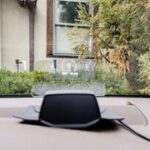
Figure 13: The display with a temporary white cable used for testing
The digital speedometer OBD2 has been tested and shown to be accurate within 1kph compared to GPS-derived speed.
Customization and Further Modifications for Your Digital Speedometer OBD2
The software for this digital speedometer OBD2 is highly customizable. You can modify it to display various other OBD-II parameters, provided your vehicle supports them. Important Note: OBD-II parameter support varies between manufacturers. Always verify parameter availability using OBD-II monitoring software before making changes.
While fuel tank level might seem like a useful parameter, it’s often not available via OBD-II, as is the case with Mitsubishi Pajero. However, parameters like engine coolant temperature, RPM, and even performance metrics like 0-60 mph time can be implemented.
The provided source code is well-commented and written in Bascom, a user-friendly BASIC-like language for AVR microcontrollers, making modifications relatively easy. You can replace the oil temperature bar graph with additional numeric displays or implement logging functions. The spare pin on the ATtiny85 and available code space allow for future feature additions like speed alerts or display mode selection.
Automatic power on/off functionality is a potential future enhancement to further refine your digital speedometer OBD2.
Conclusion: A Safer and More Informative Driving Experience with Digital Speedometer OBD2
This DIY digital speedometer OBD2 project provides a cost-effective and highly functional solution to speedometer visibility problems and opens the door to creating custom automotive gauges. By leveraging the OBD-II interface and readily available components, you can enhance your driving experience with clear, real-time vehicle data displayed directly in your line of sight. Driving in challenging conditions becomes safer and more informed with this digital speedometer OBD2 upgrade.
Downloads
- Software (HEX file & Bascom source code)
- 3D Printer File (STL format)
- Extreme USBasp Files
Click here to return to the main page.
© 2015 Andrew Woodfield ZL2PD Template design by Andreas Viklund