Want to understand what’s going on under the hood of your car without relying on expensive mechanics? Building your own OBD2 adapter is a fantastic DIY project that empowers you to read diagnostic codes and monitor your vehicle’s health. This guide will walk you through creating a simple yet effective OBD2 adapter, allowing you to tap into your car’s onboard computer using readily available tools and parts.
Disclaimer: Before we dive in, it’s crucial to understand that this project is undertaken at your own risk. While this guide is based on proven methods, I am not a professional mechanic or electronics expert. Incorrect wiring or handling can potentially damage your car’s ECU or other systems. By proceeding, you acknowledge and accept these risks. If you’re uncomfortable with any of these steps, it’s always best to consult with a qualified professional. Let’s get started and build your Diy Obd2 Adapter!
Tools and Parts You’ll Need
To embark on this project, gather the following essential tools and components:
- Wire Strippers/Cutters: For preparing the wires by removing insulation and cutting them to the desired length.
- Needle-Nose Pliers: Helpful for manipulating small components, especially when crimping or soldering.
- Molex Crimping Tool (Optional but Recommended): While not strictly necessary, a crimping tool makes securing the pins to the wires much easier and more reliable.
- Soldering Iron (Recommended): Soldering provides a robust and electrically sound connection. While crimping alone can work, soldering adds an extra layer of security, especially for delicate wiring.
- 4-Pin Connector: This connector will interface with your chosen OBD2 cable. Ensure it’s compatible with the wire gauge you’ll be using. A suitable option is available at Corsa Technic 4-Pin Connector (pin/wire size = 22-16AWG; insulation/seal size = 1.3-1.7mm).
- OBD-II Cable: This cable provides the OBD2 connector that plugs into your car. You can find a suitable cable at Corsa Technic OBD-II Cable. Alternatively, you can source a female OBD-II connector separately if you prefer to use your own wiring.
If you have spare wires and only purchase the female OBD-II connector and 4-pin connector, ensure you have wires of the correct gauge for the chosen connectors.
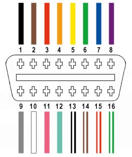
Understanding the OBD2 Wiring
The OBD2 connector has 16 pins, but for our basic DIY adapter, we only need to focus on four essential connections:
- Pin 4 (Chassis Ground): Provides the ground connection, typically an orange wire in the specified OBD2 cable (OBD2C).
- Pin 6 (CAN [J-2234] High): Carries the CAN bus high signal, a green wire in the OBD2C.
- Pin 14 (CAN [J-2234] Low): Carries the CAN bus low signal, a brown wire with a white stripe in the OBD2C.
- Pin 16 (Battery Power): Supplies power, a green wire with a white stripe in the OBD2C.
Understanding OBD2 Connector Pins for DIY Adapter Building
Step-by-Step Guide to Building Your DIY OBD2 Adapter
Let’s get hands-on and build your OBD2 adapter. Follow these steps carefully:
Step 1: Preparing the OBD2 Cable Wires
Start by preparing the OBD2 cable. It’s often recommended to twist pairs of wires for signal integrity, especially for CAN bus communication. Begin by carefully removing the outer sheath and shielding from the OBD2 cable (OBD2C) to access the internal wires. Identify and separate the four wires we’ll be using: Pin 4 (orange), Pin 6 (green), Pin 14 (brown/white), and Pin 16 (green/white). Bundle the remaining 12 wires together and secure them with a zip tie to keep them out of the way during the assembly process.
Stripping the Sheath and Shielding from the OBD2 Cable for DIY Adapter Project
Isolating the Four Essential Wires for DIY OBD2 Adapter Construction
Step 2: Preparing the Wire Ends for the 4-Pin Connector
A slight challenge arises because the wires in the OBD2 cable are often 26AWG, which is thinner than the 22AWG pin size of the 4-pin connector (4PC). To compensate for this difference, carefully strip approximately 3/8″ of insulation from the end of each of the four selected wires. Fold the exposed wire strands back over themselves and twist them tightly to effectively thicken the wire gauge, making it a better fit for the 4-pin connector pins. Slide one of the rubber seals (included with the 4PC kit) onto each wire. These seals provide environmental protection for the connection.
Thickening Wire Ends and Adding Seals for Secure Connection to 4-Pin Connector
Step 3: Attaching Wires to the 4-Pin Connector Pins
Now, take the pins from the 4-pin connector kit. Each pin has two sets of prongs. The front prongs are designed to crimp onto the exposed wire, and the rear prongs crimp onto the wire seal. Insert a prepared wire into a pin, ensuring the exposed wire aligns with the front set of prongs. Due to the thin gauge of the wire compared to the pin, you might need to use needle-nose pliers to hold the wire securely in place while proceeding to the next step.
Comparing Thin OBD2 Wire Gauge to the Larger 4-Pin Connector Pin Size
Step 4: Soldering the Wires to the Pins (Recommended)
Soldering the wires to the connector pins is highly recommended for a reliable and durable connection. Solder provides a solid electrical bond and mechanically reinforces the connection, especially beneficial given the small wire gauge. If you’re new to soldering, numerous online resources, like this helpful YouTube video, can provide valuable tips and techniques. Carefully apply solder to create a secure joint between the wire strands and the pin.
Soldering the Wire to the Connector Pin for a Robust Electrical Connection
Step 5: Crimping the Front Prongs (Alternative to Soldering)
If you prefer crimping or don’t have a soldering iron, use a Molex crimping tool for the best results. However, if you lack this specialized tool, needle-nose pliers can be used with careful technique. Position the wire within the front prongs of the pin. Using the needle-nose pliers at an angle, gently begin to fold one prong over the wire, then repeat for the other prong, gradually crimping them around the wire. This YouTube video offers a visual guide on crimping techniques with pliers. For extra security, you can carefully use the pliers to further flatten the crimped prongs, although this might be considered overkill if crimped adequately.
Crimping the Front Prongs of the Connector Pin Using Needle-Nose Pliers
Close-up View of the Wire Crimped Securely within the Connector Pin’s Front Prongs
Step 6: Crimping the Rear Prongs over the Seal
Slide the rubber seal up the wire until it sits between the rear set of prongs on the connector pin. Employ the same crimping technique used for the front prongs to fold the rear prongs over the rubber seal. This secures the seal and provides strain relief for the wire.
Positioning the Rubber Seal Between the Rear Prongs of the Connector Pin Before Crimping
Crimping the Rear Prongs of the Connector Pin to Secure the Rubber Seal
Finished Connector Pin with Both Wire and Seal Crimped Securely
Step 7: Twisting Wire Pairs (Recommended for CAN Bus)
While the exact reason isn’t always explicitly stated, it’s a good practice, especially for CAN bus signals, to twist the wire pairs. Pair and twist the wires as follows:
- Pin 4 (orange) / Pin 16 (green/white)
- Pin 6 (green) / Pin 14 (brown/white)
This twisting helps to reduce electromagnetic interference and improve signal quality, particularly for the CAN bus communication lines.
Step 8: Inserting Pins into the 4-Pin Connector Housing
Finally, insert the completed pins into the 4-pin connector housing (4PC) in the correct orientation as shown below:
- Pin 14 (brown/white) > Connector Slot A
- Pin 6 (green) > Connector Slot B
- Pin 16 (green/white) > Connector Slot C
- Pin 4 (orange) > Connector Slot D
Push each pin in from the rear of the connector until you hear a distinct “click,” indicating that the pin is securely locked in place. You might find needle-nose pliers helpful for gently pulling the wire from the front to ensure the pin is fully seated and locked.
Diagram Showing Correct Pin Insertion Order into the 4-Pin Connector Housing
Testing Your DIY OBD2 Adapter
Congratulations! Your DIY OBD2 adapter is now complete.
Completed DIY OBD2 Adapter Ready for Use
DIY OBD2 Adapter Alongside a Vehicle’s OBD2 Port
You can now test your adapter by connecting it to your vehicle’s OBD2 port and using a compatible OBD2 scanner or software. The adapter was successfully tested to read and clear a self-induced error code.
DIY OBD2 Adapter Successfully Used to Diagnose and Clear an Error Code
If any step is unclear or you encounter issues, don’t hesitate to ask for clarification. Enjoy the power of DIY car diagnostics!