For automotive enthusiasts and DIY mechanics, understanding and diagnosing vehicle issues is crucial. The OBD2 (On-Board Diagnostics II) port in your car is the gateway to accessing valuable diagnostic information. While professional OBD2 scanners can be costly, creating your own Diy Obd2 To Usb Code Reader setup can be a rewarding and budget-friendly alternative. This guide will walk you through building a key component for such a system: an OBD2 to 4-pin adapter cable. This cable is a foundational step for connecting your vehicle’s OBD2 port to various DIY diagnostic tools, potentially leading to a USB interface for data analysis on your computer.
Disclaimer: Before we begin, it’s essential to understand that this project involves working with your vehicle’s electrical system. While this guide is intended to be helpful, it’s not a substitute for professional expertise. Proceed at your own risk. Improper wiring can potentially damage your vehicle’s ECU or other components. We are not responsible for any issues that may arise from following these instructions.
Tools and Parts for Your DIY OBD2 Adapter
To embark on this DIY journey, you’ll need a few essential tools and parts. Gathering everything beforehand will ensure a smoother and more efficient build process.
Tools:
- Wire Strippers/Cutters: Essential for preparing the wires by removing insulation and cutting them to the desired length.
- Needle-Nose Pliers: These will be invaluable for manipulating small components, especially when crimping or soldering.
- Molex Crimping Tool (Optional but Recommended): A crimping tool provides a secure and professional connection for the pins. While optional, it’s highly recommended for reliability.
- Soldering Iron (Recommended): Soldering offers a robust and electrically sound connection, especially for the fine wires used in this project. It’s recommended for enhanced durability.
Parts:
- 4-Pin Connector: This connector will serve as one end of your adapter cable, linking to your chosen diagnostic interface. Ensure it’s compatible with your intended use (pin/wire size = 22-16AWG; insulation/seal size = 1.3-1.7mm). You can find a suitable connector here.
- OBD-II Cable: This cable provides the OBD2 connector that plugs into your vehicle. A pre-made cable simplifies the wiring process. You can acquire an OBD-II cable here.
For budget-conscious builders, you can opt to purchase just the female OBD-II connector and use spare wires you may have on hand. This requires sourcing the correct gauge wire to match the 4-pin connector specifications.
Understanding the OBD2 Connector Wiring
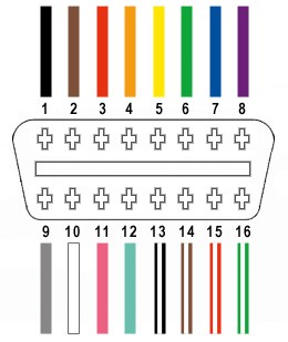
The OBD2 connector (OBD2C) is a 16-pin interface, but for this DIY adapter, we will only be utilizing four key pins. These pins are crucial for basic CAN bus communication, which is commonly used for vehicle diagnostics.
The four essential wires we’ll be working with are:
- Pin 4 (Chassis Ground): Provides the ground reference for the electrical circuit (Orange wire on the OBD2C in this example).
- Pin 6 (CAN [J-2234] High): Carries the CAN bus high signal for communication (Green wire on the OBD2C).
- Pin 14 (CAN [J-2234] Low): Carries the CAN bus low signal for communication (Brown wire with white stripe on the OBD2C).
- Pin 16 (Battery Power): Provides power to the OBD2 interface (Green wire with white stripe on the OBD2C).
Step-by-Step Guide to Building Your OBD2 to 4-Pin Adapter
Now, let’s get hands-on and assemble your DIY OBD2 adapter cable. Follow these steps carefully to ensure a successful build.
Step 1: Preparing the OBD2 Cable Wires
Many guides recommend twisting pairs of wires for better signal integrity, especially in automotive environments. Begin by carefully removing the outer sheath and shielding from the OBD2 cable to access the individual wires. Identify the four wires corresponding to pins 4, 6, 14, and 16 as listed above. Separate these four wires from the rest and neatly secure the remaining 12 wires out of the way using a zip tie or electrical tape. This keeps your workspace organized and prevents accidental connections.
Step 2: Preparing the Wire Ends for the 4-Pin Connector
The OBD2 cable wires are often very thin (26AWG), while the pins for the 4-pin connector (4PC) are designed for slightly thicker wires (22AWG). To ensure a secure connection, we need to thicken the wire ends. Carefully strip approximately 3/8″ of insulation from the end of each of the four selected wires. Fold the exposed wire strands back over the insulation and twist them together tightly. This effectively doubles the wire thickness, making it a better fit for the 4-pin connector pins. Slide a rubber seal (provided with the 4PC kit) onto each prepared wire. These seals provide environmental protection to the connection.
Step 3: Attaching Pins to the Wires
The pins for the 4-pin connector have two sets of prongs. The front prongs are designed to crimp onto the wire itself, while the rear prongs crimp onto the wire insulation (or in our case, the rubber seal). Insert the prepared wire into the pin, ensuring the exposed wire aligns with the front set of prongs. Use needle-nose pliers to hold the wire in place during the next step, as the thin wire can be tricky to manage.
Step 4: Soldering the Wires to the Pins (Recommended)
Soldering provides a superior electrical and mechanical connection, especially beneficial for these delicate wires. If you are comfortable with soldering, apply a small amount of solder to the area where the wire meets the front prongs of the connector pin. This creates a strong and reliable bond. If you are new to soldering, numerous online resources like this YouTube video can offer helpful tips and techniques.
Step 5: Crimping the Front Prongs (Alternative to Soldering)
If you prefer crimping or don’t have soldering equipment, use a Molex crimping tool for the best results. If a crimping tool isn’t available, needle-nose pliers can be used as a substitute. Carefully fold one of the front prongs over the wire using the pliers, then repeat with the other prong, ensuring a tight crimp. This YouTube video provides a visual guide on using pliers for crimping. For added security, you can gently squeeze the crimped prongs further with pliers.
Step 6: Crimping the Rear Prongs for Strain Relief
Slide the rubber seal up the wire until it sits between the rear prongs of the connector pin. Use the same crimping technique with pliers (or a crimping tool) to fold the rear prongs over the rubber seal. This provides strain relief and environmental sealing for the connection, enhancing its durability.
Step 7: Wire Pairing and Twisting (Recommended)
While the exact reason isn’t definitively stated, many DIY guides recommend twisting specific wire pairs. This practice likely helps to reduce electromagnetic interference. Pair and twist the wires as follows:
- Pin 4 (Orange) & Pin 16 (Green w/white stripe)
- Pin 6 (Green) & Pin 14 (Brown w/white stripe)
(Unfortunately, an image of the twisted pairs is not available.)
Step 8: Inserting Pins into the 4-Pin Connector Housing
Finally, insert the completed pins into the 4-pin connector housing (4PC) in the correct orientation as shown below:
- Pin 14 (Brown w/white stripe): Connector slot A
- Pin 6 (Green): Connector slot B
- Pin 16 (Green w/white stripe): Connector slot C
- Pin 4 (Orange): Connector slot D
Push each pin into the rear of the connector housing until you hear a click, indicating it is securely locked in place. Needle-nose pliers can be helpful for gently pulling the wire from the front to ensure the pin is fully seated and locked.
Your DIY OBD2 Adapter is Complete!
Congratulations! You have successfully built your own DIY OBD2 to 4-pin adapter cable.
This adapter can now be used as part of your DIY OBD2 to USB code reader setup. When combined with a suitable diagnostic interface and software, you can read and clear error codes, monitor vehicle parameters, and gain valuable insights into your car’s health.
If any step is unclear, please refer back to the images or seek additional online resources for clarification. With careful execution, this DIY project can empower you with valuable automotive diagnostic capabilities.