Every seasoned mechanic and automotive enthusiast understands that precision is paramount. Whether you’re restoring a classic, modifying your ride for performance, or tackling essential repairs, accuracy in every component is non-negotiable. This is where the art and science of drafting, specifically creating detailed Drawings Of Car Parts, steps into the limelight.
While the term “machining” might conjure images of roaring engines and gleaming chrome, the true foundation of any successful automotive project lies in meticulous planning and design. Think of it as the difference between haphazardly hammering away at a piece of metal in hopes of fabricating a part, versus methodically crafting a component to exact specifications, ensuring a perfect fit and optimal performance right from the start.
The benefits of embracing technical drawing for car parts are undeniable. You’ll not only accelerate your build times but also drastically reduce material waste and achieve a superior, more professional finish. Imagine creating that custom bracket, not through trial and error, but by designing it precisely on paper (or digitally) first, guaranteeing it fits perfectly the first time you fabricate it.
So, what exactly is technical drawing or drafting in the automotive context? In essence, it’s the language of engineering and manufacturing, a visual communication system that clearly illustrates the function and construction of a part. It’s about creating drawings of car parts that leave no room for ambiguity, ensuring everyone from the designer to the fabricator is on the same page.
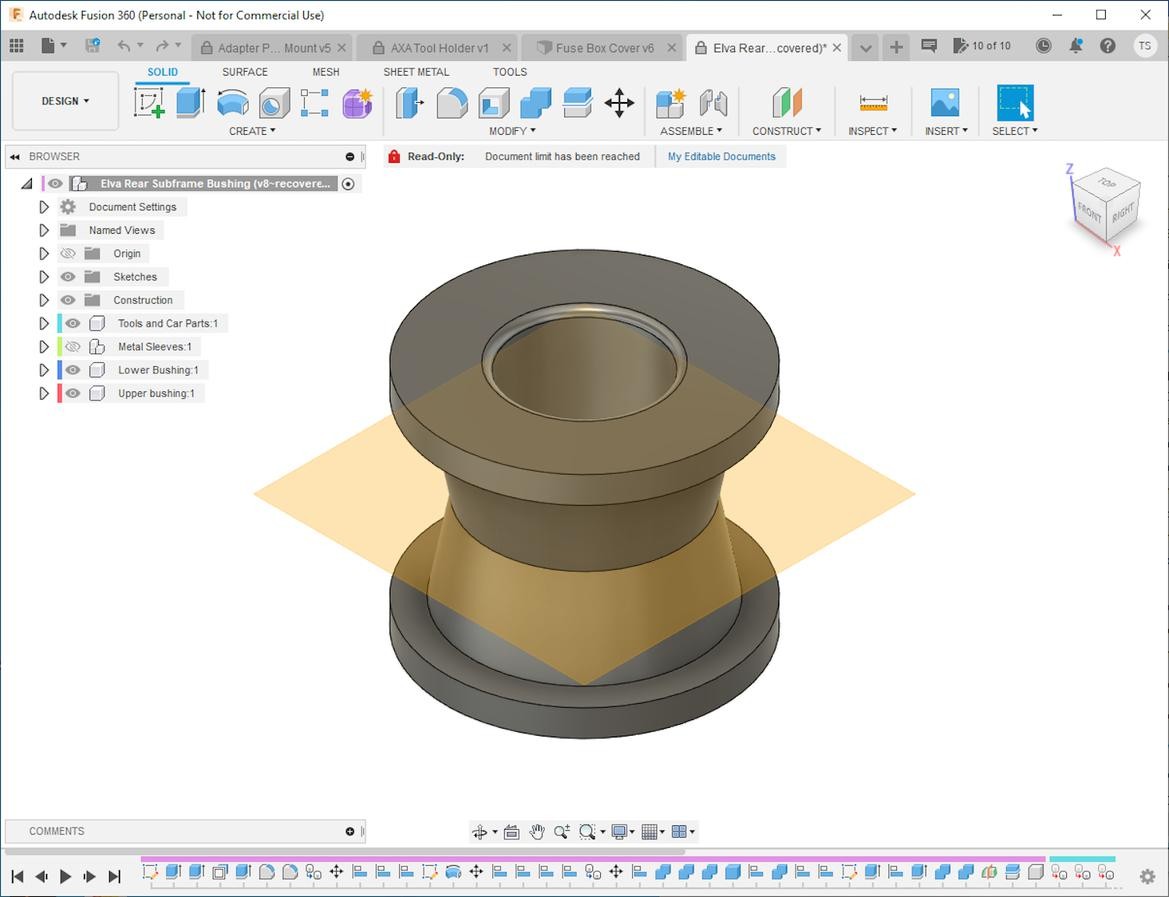
In today’s digital age, creating drawings of car parts has never been more accessible. Software like Autodesk Fusion 360 brings powerful computer-aided design (CAD) to your fingertips, allowing you to visualize part interactions and refine your designs with ease.
You might be surprised to realize you’ve already dabbled in drafting, perhaps without even recognizing it. Remember sketching out a simple bracket for a custom car modification, jotting down dimensions, and noting drill hole sizes? Congratulations, you’ve already created a basic technical drawing. This fundamental skill is the stepping stone to mastering more intricate drawings of car parts.
The significance of technical drawings becomes even clearer when considering the essential communication between engineers and machinists. These professionals, while both crucial to the automotive world, often speak different “languages.” Technical drawings serve as the universal translator, the shared language that bridges the gap between design intent and physical realization. Engineers use drawings of car parts to articulate their vision, and machinists rely on them to understand the precise requirements for manufacturing those parts.
If your ambition is to craft your own bespoke car components in your garage, then becoming proficient in both engineering principles and machining techniques is essential. And the journey begins with mastering the creation and interpretation of technical drawings.
Engineering Your Automotive Visions: From Concept to Car Part Drawings
Engineering, at its core, is the application of scientific principles to design solutions. In the automotive context, this translates to designing everything from complex engine components to simple brackets. Even if you’ve fabricated a basic car part, you’ve already engaged in a form of engineering, albeit perhaps on a smaller scale than automotive giants.
However, the traditional approach of “eyeballing” a design directly onto metal, relying more on instinct than precise planning, has its limitations. The real paradigm shift occurs when you start prioritizing the drawing process before physically crafting the part. This means taking the time to create detailed drawings of car parts, not as an afterthought, but as the initial and crucial step in your project.
Instead of immediately diving into fabrication, invest a few minutes to sketch out your car part design. Whether it’s a complex suspension component or a simple mounting bracket, start by creating a visual representation. Then, meticulously add dimensions for every line, curve, and feature, including the precise location and size of any holes or cutouts. Congratulations, you’ve just completed your first genuine technical drawing of a car part!
By creating these drawings of car parts, you are translating your automotive ideas into a universal language understood by fabricators worldwide. Suddenly, the possibilities expand exponentially. The creation of your designed part no longer solely depends on your own hands. A fellow enthusiast, a local machine shop, or even your future self, years down the line when you need a replacement part and have forgotten the exact dimensions, can accurately recreate your design from your technical drawing.
Technical drawings and engineering are inextricably linked. Creating drawings of car parts forces you to confront potential design flaws, such as interferences or structural weaknesses, in the virtual realm of paper or CAD, rather than expensively discovering them after fabrication. Conversely, these drawings empower you to use mathematical principles to calculate precise dimensions, eliminating guesswork and ensuring accuracy from the outset.
Parametric Design: Revolutionizing Car Part Drawings
Before delving deeper into the world of drawings of car parts, it’s crucial to grasp the concept of parametric design. Parametric design might sound complex, but it’s a powerful methodology that simplifies the creation and modification of intricate designs.
Imagine describing a square not just as “a square,” but as a set of interconnected lines and constraints: “Four lines of equal length, joined at coincident points with 90-degree angles at each corner.” This is the essence of parametric design. Instead of defining absolute shapes, you define relationships and constraints between design elements.
For example, if you dimension one side of your parametric square to be 2 inches, the constraints automatically dictate that all other sides must also be 2 inches. Now, extend this concept to creating a cube from your square. A traditional drawing might simply state “a cube.” However, a parametric drawing defines the cube by extruding your constrained square into a solid object with a height equal to the square’s side length.
The true power of parametric design emerges when you need to make modifications. If you realize your initial 2-inch square is too small and change it to 3 inches, the parametric constraints automatically update the entire design. The cube instantly resizes to 3 inches on all sides because its dimensions are parametrically linked to the initial square.
Parametric design is the industry standard in modern CAD software, and while it might seem initially daunting, its flexibility and efficiency will quickly make it an indispensable tool for creating and modifying drawings of car parts.
CAD Software: Unleashing the Power of Digital Car Part Drawings
Creating parametric drawings of car parts with pencil and paper can quickly become cumbersome and inefficient. Fortunately, computer-aided design (CAD) software offers a far superior solution. CAD software has become increasingly accessible and user-friendly, making it an essential tool for anyone serious about designing and fabricating car parts.
The days of needing specialized training or expensive software to create professional drawings of car parts are long gone. User-friendly programs like Autodesk Fusion 360 have democratized CAD, offering powerful features even in free or hobbyist versions.
Utilizing Fusion 360, we designed this custom mount for a fire suppression system control box for a 350Z roll cage. CAD allows for elegant and precise solutions, eliminating the need for makeshift fixes. By defining parameters and constraints, we finalized the design virtually, minimizing material waste and prototyping.
With readily available online tutorials and intuitive interfaces, learning the basics of CAD for drawings of car parts is surprisingly quick. Within a short time, you can be designing components more complex than you might initially imagine fabricating with traditional methods. Fusion 360, along with other excellent alternatives, offers a comprehensive suite of features ideal for home garages and automotive workshops.
The best approach to learning CAD is often hands-on. Explore different software options, see what your peers are using, and dive into online tutorials. The internet is a treasure trove of resources to guide you through the intricacies of creating drawings of car parts in CAD.
Virtual Engineering: Designing Car Parts in the Digital Realm
Once you understand the fundamentals of drafting, parametric design, and CAD software, you can begin to truly harness the power of virtual engineering. You’ll quickly realize that CAD is more than just a drawing tool; it’s a virtual workshop where you can experiment, innovate, and solve design challenges before ever touching physical materials.
Instead of struggling to visualize complex assemblies in your mind, CAD allows you to draw all interacting components, including the stock material you plan to use. You can then virtually “assemble” these parts within the software, using its collision detection and analysis tools to identify potential interferences, clearance issues, and material requirements.
This virtual engineering environment provides a powerful “X-ray vision” into your designs. You can assess structural integrity, optimize material usage, and refine complex geometries with ease. Creating drawings of car parts in CAD becomes an iterative process of design, analysis, and refinement, all within the digital realm. Mistakes are easily rectified with a few clicks, and design revisions are non-destructive, saving both time and resources.
Practice is the key to mastering CAD-based engineering. Experiment with different design approaches, explore software features, and don’t hesitate to search online forums and tutorials whenever you encounter a challenge. The virtual environment of CAD empowers you to learn through experimentation, turning design obstacles into learning opportunities.
From Digital Car Part Drawings to Physical Reality
After designing your car parts in CAD and creating detailed drawings of car parts on your computer screen, the next step is bringing those virtual creations into the physical world. This involves translating your digital designs into instructions that can be understood by manufacturing processes.
Fortunately, CAD software streamlines this process. Most programs can automatically generate technical drawings from your 3D models, creating 2D views with dimensions, annotations, and manufacturing information. With a bit of customization, you can quickly produce professional-looking drawings of car parts ready for fabrication.
A critical aspect of these drawings is the inclusion of tolerances. Tolerances define the acceptable margin of error for each dimension, indicating how precise the manufactured part needs to be. Specifying tolerances on your drawings of car parts is crucial for ensuring proper fit and function. A machinist relies on these tolerances to understand the required level of precision during fabrication.
With your detailed drawings of car parts in hand, you’re ready to move to the fabrication stage. This could involve machining the parts yourself, outsourcing to a local machine shop, or even utilizing online fabrication services.
The future of car part fabrication is here: We 3D-printed this mount in-house, directly from our CAD design. This rapid prototyping and manufacturing capability, which we will explore further, is revolutionizing how custom car parts are created.
Even if you plan to fabricate the parts yourself using existing tools, creating drawings of car parts will significantly improve your accuracy and efficiency. For complex parts or when outsourcing fabrication, detailed drawings are essential for clear communication and accurate results. Presenting a machine shop with professional drawings of car parts transforms you from a casual hobbyist into a serious client, increasing the likelihood of a positive and efficient collaboration.
The digital age has also opened doors to online machine shops. You can upload your 3D CAD models and drawings of car parts to these services and have custom parts manufactured and shipped directly to you. While online machining offers convenience, remember that short-run custom parts can still be a significant investment.
If you’re committed to DIY car part fabrication and want to expand your capabilities, the next logical step is exploring machining equipment. This will be the focus of the next installment in our series, building upon the foundation of creating effective drawings of car parts.