When your check engine light illuminates and your OBD2 scanner reads a P1516 code on a GM vehicle, it signals a problem within the Throttle Actuator Control (TAC) system. This code, specifically “Throttle Actuator Control (TAC) Module Throttle Actuator Position Performance,” indicates that the engine control module (ECM) has detected a discrepancy between the commanded and actual throttle position. Diagnosing this issue effectively is crucial for restoring your vehicle’s performance. This guide provides a step-by-step approach to testing the key components of the TAC system using a Digital Multimeter (DMM), helping you pinpoint the source of the P1516 code.
Understanding the P1516 Code and TAC System
The P1516 code is a common trouble code in GM vehicles, often related to issues within the electronic throttle control system. This system relies on several components working in harmony:
- Throttle Actuator Control (TAC) Module: This module interprets signals from the accelerator pedal and commands the throttle plate to open or close accordingly.
- Throttle Actuator Motor: The motor physically moves the throttle plate based on commands from the TAC module.
- Throttle Position Sensor (TPS): The TPS monitors the throttle plate’s angle and sends this information back to the ECM and TAC module.
- Accelerator Pedal Position (APP) Sensor: Located at the accelerator pedal, this sensor detects the driver’s input and sends signals to the TAC module, indicating the desired throttle position.
A P1516 code can arise from malfunctions in any of these components or their related wiring. Testing these components with a DMM is a fundamental step in diagnosing the problem.
Testing the TAC System with a DMM for P1516 Code
Before proceeding with these tests, ensure the ignition is off and the key is removed for at least 15 seconds to allow the system to fully power down.
1. TAC Motor Test
This test verifies the TAC motor’s ability to respond to voltage commands.
Steps:
- Disconnect the TAC Motor connector.
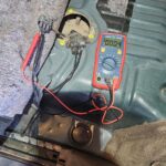
- Set your DMM to Volts DC mode, selecting a range above 12V.
- Backprobe the Yellow wire (TAC motor CNTRL 1) with the DMM’s red lead.
- Backprobe the Brown wire (TAC motor CNTRL 2) with the DMM’s black lead.
- Turn the Key On, Engine Off (KOEO).
- Voltage Reading: You should read approximately 12V. This indicates power is being supplied to the TAC motor circuit.
- Throttle Snap Test: Quickly depress and release the accelerator pedal (snap throttle). The polarity reading on your DMM should reverse momentarily. This indicates the TAC module is attempting to control the motor.
- Key OFF and reconnect the TAC motor connector.
2. Throttle Position Sensor (TPS) Test
This test assesses the voltage signals from the TPS as the throttle plate moves.
Steps:
- Set your DMM to Volts DC mode, selecting a range above 5V.
- Backprobe the Dark Green wire (TPS Signal 1) with the DMM’s red lead.
- Connect the DMM’s black lead to a known good ground. Ensure a solid ground connection for accurate readings.
- Start your truck (Key On, Engine Running – KOER).
- Closed Throttle Voltage: With the throttle closed (idle position), you should read approximately 4V.
- Open Throttle Voltage (Signal 1): Slowly open the throttle. As you open the throttle, the voltage reading should decrease. At Wide Open Throttle (WOT), the voltage should be near 1V. A rapid voltage change during a slow throttle movement indicates a functioning sensor. A scope would be ideal for capturing fast changes during a snap throttle, but a DMM with MIN/MAX function might help capture voltage fluctuations.
- Move DMM test leads to:
- Backprobe the Purple wire (TPS Signal 2) with the DMM’s red lead.
- DMM black lead remains on a known good ground.
- Closed Throttle Voltage (Signal 2): With the throttle closed, you should read approximately 1V (opposite of TPS Signal 1).
- Open Throttle Voltage (Signal 2): As you open the throttle, the voltage reading should increase. At WOT, the voltage should be around 3.5 – 4V (opposite of TPS Signal 1).
- Key OFF.
3. Accelerator Pedal Position (APP) Sensor Test
This test checks the voltage signals from the APP sensor as the accelerator pedal is depressed.
Steps:
- Locate the APP sensor connector above the accelerator pedal (leave it connected).
- Set your DMM to Volts DC mode, selecting a range above 5V.
- Backprobe the Dark Blue wire or Dark Blue/White wire (APP Sensor SIGNAL 1) with the DMM’s red lead.
- Connect the DMM’s black lead to a known good ground.
- Key On, Engine Off (KOEO).
- Pedal Up Voltage (Signal 1): With the accelerator pedal fully released (up), the voltage should be below 1V.
- Pedal Down Voltage (Signal 1): Slowly depress the accelerator pedal fully. As you depress the pedal, the voltage should increase to above 4V at full depression.
- Move DMM red lead to backprobe the Light Blue wire (APP sensor SIGNAL 2).
- Pedal Up Voltage (Signal 2): With the pedal fully released, the voltage should be around 4V.
- Pedal Down Voltage (Signal 2): As you depress the pedal fully, the voltage should decrease to less than 1V at full depression.
Interpreting Test Results and Next Steps
These DMM tests provide valuable insights into the health of your TAC system components. Incorrect voltage readings or a lack of voltage change as expected during these tests can indicate a faulty sensor, motor, wiring issue, or a failing TAC module.
If your tests reveal discrepancies, further investigation is warranted. Check for:
- Wiring Issues: Inspect connectors and wiring harnesses for damage, corrosion, or loose connections.
- Sensor or Motor Failure: Replace suspected faulty components based on test results.
- TAC Module Malfunction: If sensors and wiring are good, the TAC module itself may be the problem.
Resolving a P1516 code can sometimes require advanced diagnostic tools and expertise. If you are uncomfortable performing these tests or the code persists after component replacement, it’s recommended to consult a qualified automotive technician. They can perform more in-depth diagnostics, including using a scan tool to monitor live data and potentially perform TAC module reprogramming if necessary. By systematically testing the TAC system, you can effectively troubleshoot the P1516 code and restore your GM vehicle’s optimal throttle control performance.