For car enthusiasts and DIYers, accessing your vehicle’s diagnostic data can be incredibly useful. An OBD2 to USB cable allows you to connect your car’s On-Board Diagnostics II (OBD2) port to your computer, opening up a world of possibilities for reading error codes, monitoring performance, and understanding your vehicle’s health. While you can purchase pre-made cables, building your own “How To Make Obd2 To Usb Cable” is a rewarding project that can save you money and deepen your understanding of automotive electronics. This guide provides a step-by-step approach to creating your own OBD2 to USB cable, perfect for connecting to diagnostic software and tools.
Before we begin, it’s important to understand that this is a DIY project and involves working with electrical components. While this guide aims to be as clear and safe as possible, you are undertaking this project at your own risk. Improper wiring or handling can potentially damage your vehicle’s electronic control unit (ECU) or other systems. If you are not comfortable working with electronics, it is recommended to purchase a pre-made OBD2 to USB cable from a reputable source.
Tools and Parts You’ll Need
To successfully “how to make obd2 to usb cable”, gather the following tools and parts:
- Wire strippers/cutters: Essential for preparing wires for connection.
- Needle-nose pliers: Helpful for manipulating small components and wires.
- Molex crimping tool (recommended): While not strictly required, a crimping tool provides a more secure and professional connection for the connector pins.
- Soldering iron (recommended): Soldering offers a robust and reliable connection, especially for the fine wires used in OBD2 cables.
- 4-Pin Connector: This connector will interface with your chosen USB adapter (e.g., TTL serial to USB). Ensure it’s compatible with your adapter and wire gauge. (Example 4-Pin Connector; pin/wire size = 22-16AWG; insulation/seal size = 1.3-1.7mm)
- OBD-II Cable: This cable provides the OBD2 connector that plugs into your vehicle. (Example OBD-II Cable)
If you have spare automotive wire available, you can purchase just the female OBD-II connector and wire the necessary connections directly to your 4-pin connector, potentially saving on costs. However, ensure you use the correct wire gauge and that the 4-pin connector is compatible with your wire size.
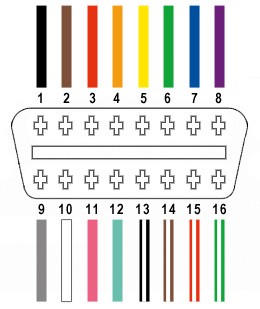
From the 16 pins available on the OBD-II connector (referred to as OBD2C), we will only be using four critical pins for basic OBD2 functionality:
- Pin 4: Chassis Ground (often an orange wire on the example OBD2C)
- Pin 6: CAN High (CAN [J-2234] High; often a green wire on the example OBD2C)
- Pin 14: CAN Low (CAN [J-2234] Low; often a brown wire with a white stripe on the example OBD2C)
- Pin 16: Battery Power (often a green wire with a white stripe on the example OBD2C)
These pins are essential for establishing communication with your vehicle’s CAN bus network, which is used for diagnostics in most modern cars.
Step-by-Step Guide: Building Your OBD2 to USB Cable
Let’s walk through the process of “how to make obd2 to usb cable” step-by-step:
Step 1: Preparing the OBD2 Cable
Many guides recommend twisting pairs of wires to reduce electromagnetic interference. To prepare the OBD2 cable, carefully remove the outer sheath and shielding from a section of the OBD2C cable to expose the individual wires. Identify and separate the four wires you will be using (Pins 4, 6, 14, and 16 as listed above). Bundle the remaining 12 wires together and secure them with a zip tie to keep them out of the way and prevent accidental shorts.
Step 2: Preparing the Wires for the 4-Pin Connector
A common issue when “how to make obd2 to usb cable” with readily available parts is wire gauge mismatch. The wires in many OBD2 cables are often 26AWG, while the pins for standard 4-pin connectors are designed for slightly thicker 22AWG wires. To compensate for this, carefully strip approximately 3/8″ of insulation from the end of each of the four selected OBD2 wires. Fold the exposed wire strands back over themselves, and twist them tightly to effectively thicken the wire and improve contact within the connector pin. Slide one of the rubber seals (if included with your 4-pin connector kit) over each wire. These seals provide strain relief and environmental protection.
Step 3: Attaching Pins to the Wires
The pins for the 4-pin connector typically have two sets of prongs: one set to grip the wire strands and another to grip the wire insulation (seal). Insert the prepared wire into a pin, ensuring the exposed wire is positioned to be crimped by the inner set of prongs. The wire may seem small compared to the pin, highlighting the wire gauge difference. Using needle-nose pliers can be helpful to hold the wire in place during the next step, especially if you choose to solder.
Step 4: Soldering or Crimping the Pins
This step offers two options for securing the wires to the connector pins: soldering or crimping.
- Soldering (Recommended): Soldering provides a strong, electrically sound connection, which is particularly beneficial when working with fine wires. If you choose to solder, apply a small amount of solder to the area where the inner prongs of the pin meet the twisted wire. Ensure the solder flows smoothly and creates a solid joint. Consider watching a soldering tutorial for electronics if you are new to soldering.
- Crimping (Alternative): If you have a Molex crimping tool, this is the ideal method for securing the pins. Position the pin and wire in the crimping tool according to the tool’s instructions and crimp firmly to secure the wire. If you don’t have a crimping tool, you can carefully use needle-nose pliers. Using angled needle-nose pliers, gently fold one of the inner prongs over the wire, then repeat for the other prong. A video guide on using pliers for crimping can be helpful. For added security when using pliers, you can gently squeeze the prongs further to ensure a tight grip.
Step 5: Securing the Seal and Completing Pin Attachment
Slide the rubber seal up the wire until it sits between the outer set of prongs on the connector pin. Use the same crimping or pliers technique as in Step 4 to fold these outer prongs over the rubber seal. This secures the seal, providing strain relief and environmental protection to the connection. Repeat steps 2-5 for all four wires and connector pins.
Step 6: Wire Pairing and Twisting (Recommended)
While the exact reason isn’t always explicitly stated, many DIY guides for “how to make obd2 to usb cable” recommend pairing and twisting specific wires. This is likely to further reduce electromagnetic interference and improve signal integrity, especially for the CAN bus signals. Pair and twist the wires as follows:
- Pair 1: Pin 4 (Chassis ground – orange wire in example) and Pin 16 (Battery power – green w/white stripe in example)
- Pair 2: Pin 6 (CAN High – green wire in example) and Pin 14 (CAN Low – brown w/white stripe in example)
Twist each pair of wires together along their length.
Step 7: Inserting Pins into the 4-Pin Connector Housing
Finally, insert the completed pins into the 4-pin connector housing in the correct orientation. Refer to the pinout diagram of your 4-pin connector and the following arrangement based on the example parts:
- Connector Slot A: Pin 14 (CAN Low – brown w/white stripe)
- Connector Slot B: Pin 6 (CAN High – green)
- Connector Slot C: Pin 16 (Battery power – green w/white stripe)
- Connector Slot D: Pin 4 (Chassis ground – orange)
Insert each pin into the rear of the connector housing until you hear an audible “click,” indicating that the pin is locked into place. You can use needle-nose pliers to gently pull on the wire from the rear to ensure the pin is securely seated.
Testing Your DIY OBD2 to USB Cable
Congratulations! You have now completed your DIY “how to make obd2 to usb cable” project. The final step is to test your cable. Connect the OBD2 connector to your vehicle’s OBD2 port and the 4-pin connector to your USB adapter (which should be connected to your computer). Use your chosen OBD2 diagnostic software to attempt to connect to your vehicle. If successful, you should be able to read diagnostic trouble codes (DTCs) and access other vehicle data.
If you encounter any issues, double-check your wiring, pin connections, and ensure your diagnostic software is properly configured. If you have questions or need further clarification on any step of “how to make obd2 to usb cable”, consult online forums or communities dedicated to automotive diagnostics and DIY car projects. With patience and careful execution, you can successfully build your own OBD2 to USB cable and unlock a deeper understanding of your vehicle’s inner workings.