Connecting your car’s On-Board Diagnostics II (OBD2) port to a USB interface can unlock a world of diagnostic possibilities. This DIY guide will walk you through the process of wiring an OBD2 connector to a USB, enabling you to interface with your vehicle’s computer using readily available tools and parts. Please remember, while this guide aims to be helpful, automotive electrical work should be approached with caution. Working on your car’s electronics is at your own risk. We are not responsible for any damage or issues that may arise from following these instructions.
Before you begin, gather the necessary tools and parts to ensure a smooth and efficient wiring process.
Tools and Parts You’ll Need
- Wire Strippers/Cutters: Essential for preparing wires by removing insulation.
- Needle-Nose Pliers: Useful for manipulating small parts and wires in tight spaces.
- Molex Crimping Tool (Optional but Recommended): For creating secure and professional crimp connections.
- Soldering Iron (Recommended): To enhance connection reliability, though crimping can be sufficient.
- 4-Pin Connector: A 4-pin connector is needed to interface with the OBD2 cable wires. Ensure it is compatible with wire sizes between 22-16AWG and insulation sizes between 1.3-1.7mm. (Example Connector)
- OBD-II Cable: An OBD-II cable provides the necessary wires and the OBD2 connector itself. (Example OBD-II Cable)
For cost savings, if you have spare automotive wiring available, you can purchase just the female OBD-II connector and wire it directly to the 4-pin connector, provided you use the correct gauge wire for your chosen 4-pin connector.
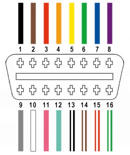
From the OBD-II connector cable (referred to as OBD2C), we will only utilize four essential wires for basic OBD2 to USB connectivity:
- Pin 4: Chassis Ground (typically an orange wire on the OBD2C)
- Pin 6: CAN High (CAN J-2234) (typically a green wire on the OBD2C)
- Pin 14: CAN Low (CAN J-2234) (typically a brown wire with a white stripe on the OBD2C)
- Pin 16: Battery Power (typically a green wire with a white stripe on the OBD2C)
Step-by-Step Wiring Guide
Let’s proceed with the wiring process. Follow these steps carefully to create your OBD2 to USB adapter.
Step 1: Prepare the OBD2 Cable
Begin by preparing the OBD2 cable. Many guides recommend twisting pairs of wires for signal integrity, especially with CAN bus systems. Start by carefully removing the outer sheath and shielding from the OBD2C to expose the internal wires. Identify and separate the four wires you’ll be using (pins 4, 6, 14, and 16 as listed above). Bundle the remaining 12 unused wires and secure them out of the way with a zip tie to keep your workspace tidy.
Step 2: Prepare the 4-Pin Connector Pins
The wires in the OBD2C are often a very fine 26AWG gauge, while the pins for the 4-pin connector (4PC) are designed for slightly thicker 22AWG wires. To ensure a secure connection, we need to slightly thicken the OBD2C wires.
The wires in the OBD2C typically come pre-stripped with a short length of exposed wire, around 1/8 inch. Carefully strip off more insulation to achieve about 3/8 inch of exposed wire. Fold this exposed wire over itself and twist the strands together. This effectively doubles the wire thickness, making it a better fit for the 4PC pins.
Next, take the rubber seals included with the 4PC kit. Slide one rubber seal onto each of the four prepared wires. These seals will provide environmental protection at the connector.
Step 3: Connect Wires to Pins (Soldering or Crimping)
Now we connect the prepared wires to the pins of the 4PC. Each pin has two sets of prongs. The front prongs are designed to crimp onto the exposed wire, and the rear prongs are for crimping onto the wire insulation seal.
Insert the exposed, thickened wire into the front part of the pin, ensuring it aligns with the front set of prongs. You’ll notice that the 26AWG wire, even when folded, appears small compared to the pin connector. Using needle-nose pliers can be helpful to hold the wire in position during the next steps.
At this point, you have a choice: soldering or crimping. Soldering provides a very robust and electrically sound connection, which is recommended, especially given the fine wire gauge.
Soldering: If you choose to solder, apply a small amount of solder to the wire where it meets the pin. Ensure the solder flows smoothly and creates a solid connection. If you are new to soldering, resources like YouTube tutorials can be very helpful in learning proper techniques.
Crimping: If you prefer crimping or do not have soldering equipment, use a Molex crimping tool for the best results. If a crimping tool is unavailable, needle-nose pliers can be used carefully.
To crimp with pliers, gently fold one of the front prongs over the wire using the pliers at an angle. Repeat for the other prong, ensuring a tight crimp. For extra security, you can carefully squeeze the prongs further down with the pliers, but avoid excessive force that could damage the pin.
Step 4: Assemble the 4-Pin Connector
Slide the rubber seal you placed on the wire up to the 4PC pin. Position the seal so it sits between the rear set of prongs on the pin. Use the same crimping technique as before (soldering is not applicable here) to fold the rear prongs over the rubber seal, securing it in place and providing strain relief and environmental protection.
Repeat steps 2-4 for the remaining three wires and 4PC pins.
Once all four pins are prepared, it’s recommended to twist specific wire pairs together. This practice, often seen in similar guides, is thought to improve signal quality, especially for CAN bus communication. Twist the following pairs together:
- Pin 4 (orange) and Pin 16 (green w/white stripe)
- Pin 6 (green) and Pin 14 (brown w/white stripe)
Step 5: Insert Pins into the 4-Pin Connector Housing
Finally, insert the completed pins into the 4-pin connector housing (4PC) in the correct orientation. The pin assignments are as follows:
- Pin 14 (brown w/white stripe) > Connector Slot A
- Pin 6 (green) > Connector Slot B
- Pin 16 (green w/white stripe) > Connector Slot C
- Pin 4 (orange) > Connector Slot D
Push each pin into the rear of the connector housing until you hear a distinct click. This click indicates that the pin is securely locked in place. Using needle-nose pliers to gently pull on the wire from the rear can help ensure the pin is fully seated and locked.
Testing Your DIY Cable
Congratulations! Your DIY OBD2 to USB cable is now complete.
You can now test your newly created cable. Connect the OBD2 end to your vehicle’s OBD2 port and the 4-pin connector end to a suitable USB adapter or interface that is compatible with OBD2 communication protocols. Use appropriate diagnostic software to verify the connection and read vehicle data.
This DIY OBD2 to USB cable provides a functional solution for basic car diagnostics. If you encounter any issues or have questions, consult online forums and communities dedicated to automotive diagnostics for further assistance. Remember to always exercise caution when working with vehicle electronics.