When diving into engine swaps or modifications on Honda Preludes, one of the first questions that often arises is about the car’s On-Board Diagnostics (OBD) system. Specifically, for those working on a fifth-generation Prelude, a common query is: Is A 96 Prelude Obd1 Or Obd2? Understanding this is crucial, especially when you’re considering engine swaps, like installing a JDM H22A engine.
The 1996 Honda Prelude chassis is indeed OBD2. This is important to establish right from the start. However, things can get a bit more complex when you introduce engines from different markets or older generations. This article will explore this topic, focusing on how to navigate installing an OBD1 engine, such as a JDM H22A, into your OBD2 96 Prelude. We’ll draw inspiration from a practical example of overcoming this very challenge, ensuring your project runs smoothly.
Understanding OBD1 and OBD2 Systems
Before we delve into the specifics of the 96 Prelude and engine swaps, it’s essential to grasp the basics of OBD1 and OBD2 systems. These are generations of automotive diagnostic systems that dictate how the car’s computer (ECU) monitors and controls various aspects of the engine and emissions systems.
-
OBD1 (On-Board Diagnostics I): This was the first generation of standardized on-board diagnostics. Systems varied widely between manufacturers, and even between models from the same manufacturer. OBD1 systems typically offered limited diagnostic information and used proprietary connectors.
-
OBD2 (On-Board Diagnostics II): OBD2 is a more advanced and standardized system mandated in the United States for all cars manufactured after 1996. OBD2 provides a wealth of diagnostic data, standardized diagnostic trouble codes (DTCs), and a universal connector. This standardization makes diagnosing and repairing vehicles much more efficient.
Knowing that a 1996 Prelude chassis is OBD2 is your starting point. However, the engine you’re working with might be designed for a different OBD system, especially if it’s a JDM (Japanese Domestic Market) engine or an older model engine.
The Challenge: OBD1 Engine in an OBD2 Chassis
Let’s consider the scenario of installing a JDM H22A engine, which is typically OBD1, into a 1996 OBD2 Honda Prelude. The core issue arises from the differences in sensor types and ECU communication protocols between OBD1 and OBD2 systems.
One key area of difference lies in the crankshaft fluctuation sensor, which is critical for engine timing and fuel delivery. OBD2 systems often rely on a Crankshaft Fluctuation Sensor (CKF), while older OBD1 engines might use a combination of Top Dead Center (TDC) and Crank Position (CKP) sensors, often integrated within the distributor.
When you place an OBD1 engine into an OBD2 chassis, the OBD2 ECU in your Prelude expects to see signals from OBD2-compliant sensors. If the engine lacks these sensors or uses different types, the ECU can get confused, preventing the engine from starting or running correctly.
The Solution: Bridging the Gap with a Conversion Harness
One effective method to overcome this OBD mismatch is to create a conversion harness, specifically for the distributor and related crankshaft/cylinder position sensors. This approach allows you to adapt the signals from the OBD1 engine’s sensors to be correctly interpreted by the OBD2 ECU.
The following steps detail how to create such a harness, inspired by a successful real-world example of installing a JDM H22A (OBD1) into a 1996 Prelude (OBD2).
Step-by-Step Guide to Creating an OBD1 to OBD2 Distributor Conversion Harness
This guide focuses on adapting the distributor signals, which is crucial for ignition and engine timing when using an OBD1 distributor on an OBD2 system.
1. Identifying the Sensors and Plugs
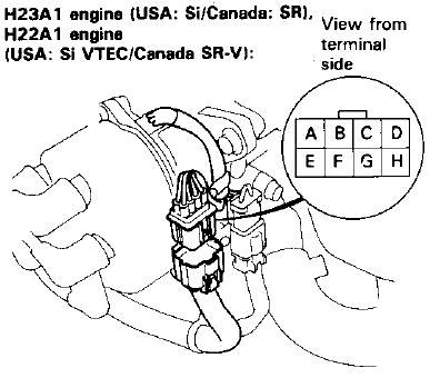
The first step is to identify the sensors on both the OBD1 distributor and the OBD2 engine harness, particularly the TDC (Top Dead Center) sensor, CKP (Crank Position) sensor, and CYP (Cylinder Position) sensor.
OBD1 distributors typically have all three signals (CKP, TDC, CYP) originating from within the distributor housing. In contrast, OBD2 systems might have separate sensors located elsewhere on the engine block.
2. Preparing the OBD1 Distributor Plug and Harness
You’ll need the OBD1 distributor plug from a JDM engine harness. Ideally, obtain this plug with some wiring attached to make splicing easier.
Carefully label each wire on the OBD1 plug to understand its function (CKP, TDC, CYP, etc.). This is crucial for correct wiring.
3. Wiring the Subharness
The goal is to create a subharness that connects the OBD1 distributor plug to the necessary sensors on the OBD2 engine harness. In this example, the focus is on using the OBD1 distributor’s signals to feed the OBD2 ECU.
Identify the CKP and TDC sensor wires from the OBD1 plug. These are the signals you need to connect to the OBD2 harness. In the example provided in the original post, the cylinder position sensor wires (CYP) were not needed directly in this subharness because the OBD2 system already handles cylinder identification through other means, or they are managed within the existing OBD2 harness setup.
4. Connecting to the OBD2 Harness and Crank Sensors
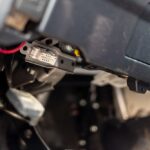
Locate the OBD2 connectors for the CKP and TDC sensors. In OBD2 Preludes, these sensors are typically found near the crankshaft and oil pump area.
OBD2 TDC and CKP sensors, typically located near the crankshaft.
In the original project, the connectors for the OBD2 TDC/CKP sensors were repurposed to connect to the OBD1 distributor signals. This involved cutting the OBD2 sensor clips and soldering the wires from the OBD1 distributor subharness to these clips.
Carefully solder and insulate the wires, matching the CKP and TDC signals from the OBD1 distributor subharness to the corresponding wires on the OBD2 sensor clips.
5. Connecting the Harness and Distributor
Connect the newly created subharness to the OBD2 engine harness at the original TDC/CKP sensor locations (typically near the oil pump). Then, route the other end of the subharness to the OBD1 distributor and plug it in.
For the distributor connection, you’ll need to address the CYP (cylinder position) and ICM (Ignition Control Module) signals. Depin the ICM, CYP+, and CYP- wires from the OBD2 distributor clip on the engine harness. Then, repin these into the OBD1 distributor subharness clip end, ensuring correct pin assignments.
6. Testing and Verification
After completing the wiring, double-check all connections and wire assignments. Start the engine to verify that it runs correctly. In the original example, the result was a successful start-up, confirming the effectiveness of this conversion method.
Conclusion
So, to definitively answer the question, a 1996 Honda Prelude chassis is OBD2. However, when performing engine swaps with OBD1 engines like the JDM H22A, understanding how to adapt the engine management system is crucial. Creating a conversion harness, particularly for the distributor and crank/cylinder position sensors, is a viable solution. By carefully following the steps outlined and referencing successful examples, you can effectively bridge the gap between OBD1 engines and OBD2 chassis, ensuring your Honda project is a success. Remember to always double-check wiring and consult wiring diagrams specific to your engine and chassis for the most accurate and safe installation.