K-Line, a predecessor to the now ubiquitous CAN bus, stands as a significant standard in OBD2 communication, particularly in European vehicles manufactured before the widespread adoption of CAN. Understanding Kline Obd2 communication is crucial for anyone delving into automotive diagnostics, repair, or ECU modification on older vehicle models. This article provides an in-depth look at K-Line OBD2, exploring its physical layer, communication protocols like KWP2000 and ISO 9141, and how to interface with it effectively.
Understanding the Physical Layer of K-Line OBD2
At its core, K-Line is essentially a single-wire, half-duplex UART (Universal Asynchronous Receiver-Transmitter) system operating at a baud rate of 10400. It utilizes voltage levels of 0V and approximately 12V (nominally battery voltage, fluctuating between 12V and 14.4V when the engine is running). This voltage level is a key differentiator from standard UARTs (0-3.3V or 0-5V) and RS-232 (+12V/-12V).
Interfacing with the K-Line from a microcontroller unit (MCU) is surprisingly straightforward. A basic circuit is sufficient to bridge the voltage gap and logic levels. The following schematic, derived from the ELM327 datasheet, illustrates a typical implementation:
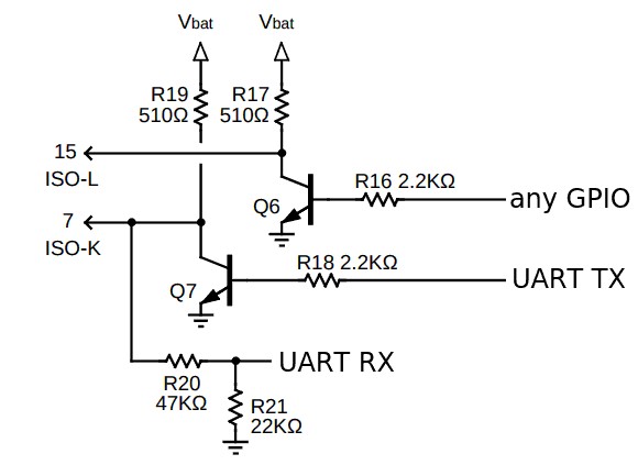 KL line schematic
Schematic diagram illustrating a typical K-Line interface circuit for OBD2 communication, showcasing voltage divider for reception and NPN transistor for transmission.
For receiving data from the K-Line, a voltage divider circuit is employed to scale down the 12V signal to a level compatible with the MCU’s input voltage (typically 5V or 3.3V). It’s essential to select resistor values that ensure the voltage at the MCU’s RX pin remains within its safe operating range, even with the voltage fluctuations on the K-Line.
Data transmission to the K-Line is managed using an NPN transistor in an open collector configuration, coupled with a pull-up resistor. A critical point to consider is that standard UART idle state is logic high. Directly connecting this to the transistor would result in a logic low on the K-Line, which is inverted. To address this, UART TX inversion should be enabled in the MCU’s peripheral settings, if supported. Microcontrollers like Kinetis E and XMEGA offer TX pin inversion, while older AVRs such as the ATmega328p may not. In the absence of TX inversion, external logic inversion circuitry using a PNP transistor or alternative methods becomes necessary.
The L-Line, often paired with K-Line in older systems (referred to as K+L or KKL), is a unidirectional transmit line from the MCU. It’s primarily used for a 5-baud wakeup sequence in older protocols, and its presence is generally limited to older vehicles.
Delving into K-Line OBD2 Protocols: KWP2000 and ISO 9141
The data for this analysis was captured using a logic analyzer, monitoring the communication between a generic ELM327 USB cable and a Freematics OBD emulator. All communication occurs at 10400 baud with 8 data bits, no parity, and 1 stop bit (8N1), except for initial pulses and slow initialization sequences. Each data frame in both protocols concludes with an 8-bit checksum, calculated as the sum of all preceding bytes in the frame, initialized to 0. This checksum is transmitted as the final byte of the frame.
KWP2000 Fast Initialization
KWP2000 fast initialization begins with a specific pulse sequence on the K-Line: a 25ms low state followed by a 25ms high state. Simultaneously, this sequence might also be applied to the L-Line, although its necessity is not definitively confirmed in official specifications. Following this pulse sequence, the initiating device (e.g., scan tool) transmits the initialization frame: 0xC1 0x33 0xF1 0x81 0x66.
Upon successful initialization request, the vehicle’s ECU should respond with a frame like: 0x83 0xF1 0x11 0xC1 0x8F 0xEF 0xC4. Validation of the response frame is crucial; the checksum of all received bytes (excluding the checksum byte itself) must match the final byte (0xC4 in this example). A valid response signifies successful initialization. The exact response may vary depending on the vehicle and model year, but for basic OBD2 functionality, any valid frame generally indicates successful initialization.
If fast initialization fails (no valid response frame received), a slow initialization procedure must be attempted, but only after a delay of at least 2.5 seconds.
KWP2000 Slow Initialization
For slow initialization, it is recommended to control the TX line as a GPIO pin, as standard UARTs might not reliably operate at the very low 5 baud rate required for the initial sequence. Software-controlled timing becomes more precise for these slow sequences. The slow initialization sequence starts with a 200ms low pulse, followed by a 400ms sequence of high/low/high/low pulses, and concludes with a 227ms high state. This sequence may also be simultaneously applied to the L-Line.
After this sequence, the ECU will respond with a 3-byte frame, for instance: 0x55 0xEF 0x8F. The values of the second and third bytes, denoted as KB1 and KB2 respectively, determine the protocol. The first byte is consistently 0x55.
If both KB1 and KB2 are either 0x08 0x08 or 0x94 0x94, the protocol is identified as ISO-9141; otherwise, it is KWP2000.
Following the ECU’s initial response, the initiating device must transmit the bitwise inverted value of KB2 back to the ECU. In our example, inverting 0x8F yields 0x70. The ECU then replies with a single byte representing its inverted ECU address, which will be used for all subsequent communication requests.
Requesting PIDs using KWP2000 Protocol
Once initialization is complete, Parameter IDs (PIDs) can be requested to retrieve diagnostic data. For KWP2000, the request frame structure is: 0xC2 <ecu_address> 0xF1 <mode> </mode></ecu_address>.
Here are examples based on ELM327 requests, which are commonly represented as commands like “010C” sent via a serial terminal to an OBD2 USB cable.
ELM Request 010C (Mode 01, PID 0x0C – RPM)
- Request Frame:
C2 33 F1 01 0C F3(ECU address0x33, mode0x01, PID0x0C, checksum0xF3) - Response Example 1:
84 F1 11 41 0C 1F 40 32(RPM value0x1F40= 8000 in decimal, actual RPM is calculated using a formula) - Response Example 2:
84 F1 11 41 0C 1F 44 36(RPM value0x1F44= 8004 in decimal)
ELM Request 010D (Mode 01, PID 0x0D – Vehicle Speed km/h)
- Request Frame:
C2 33 F1 01 0D F4 - Response Example 1:
83 F1 11 41 0D 64 37(Speed value0x64= 100 km/h) - Response Example 2:
83 F1 11 41 0D 38 0B(Speed value0x38= 56 km/h)
ELM Request 0100 (Mode 01, PID 0x00 – Supported PIDs in Mode 01)
- Request Frame:
C2 33 F1 01 00 E7 - Response:
86 F1 11 41 00 FF FF FF FF C5(Value0xFFFFFFFFindicates all PIDs from 0x01 to 0x20 are supported)
ELM Request 0902 (Mode 09, PID 0x02 – Vehicle Identification Number (VIN))
This request is unique as the VIN is typically returned in multiple frames due to its length. The VIN data is ASCII encoded and left-padded with zeros.
- Request Frame:
C2 33 F1 09 02 F1 - Response Frames:
87 F1 11 49 02 01 00 00 00 31 0687 F1 11 49 02 02 41 31 4A 43 D587 F1 11 49 02 03 35 34 34 34 A887 F1 11 49 02 04 52 37 32 35 C8
KWP2000 Keepalive Mechanism
To maintain an active communication session, ELM327 devices typically send a keepalive message every 2 seconds when no other requests are pending. Requesting PID 0x00 in mode 01 can also serve as an effective keepalive.
- Keepalive Request:
C1 33 F1 3E 23 - Keepalive Response:
81 F1 11 7E 01
Important Note: In KWP2000 responses, the first byte indicates the frame length. The length value, encoded in the lower 6 bits of this byte, excludes the length byte itself, the two type bytes, and the checksum byte. Therefore, to get the total frame length in bytes, you must add 4 to the length value provided in the first byte.
Requesting PIDs using ISO-9141 Protocol
ISO-9141 is an earlier OBD2 protocol. A significant challenge with ISO-9141 is that the response frame length is not explicitly transmitted. To handle this, two primary approaches exist: either implement a lookup table mapping PIDs to their expected response lengths, or process incoming bytes byte-by-byte, dynamically calculating the checksum and validating it against the received checksum byte, potentially incorporating timeout mechanisms to handle incomplete or erroneous responses.
Here are some examples of PID requests and responses under ISO-9141.
ELM Request 010C (Mode 01, PID 0x0C – RPM)
- Request Frame:
68 6A F1 01 0C D0 - Response:
48 6B 11 41 0C 1F 40 70(RPM value is0x1F 40)
ELM Request 0100 (Mode 01, PID 0x00 – Supported PIDs in Mode 01)
- Request Frame:
68 6A F1 01 00 C4 - Response:
48 6B 11 41 00 FF FF FF FF 01(Supported PIDs value is0xFF FF FF FF)
ELM Request 010D (Mode 01, PID 0x0D – Vehicle Speed km/h)
- Request Frame:
68 6A F1 01 0D D1 - Response:
48 6B 11 41 0D 00 12(Speed value is0x00)
ELM Request 0902 (Mode 09, PID 0x02 – VIN)
Similar to KWP2000, VIN retrieval in ISO-9141 also involves multi-frame responses.
- Request Frame:
68 6A F1 09 02 CE - Response Frames:
48 6B 11 49 02 01 00 00 00 31 41(VIN part 1 values:00 00 00 31)48 6B 11 49 02 02 41 31 4A 43 10(VIN part 2 values:41 31 4A 43)48 6B 11 49 02 03 35 34 34 34 E3(VIN part 3 values:35 34 34 34)48 6B 11 49 02 04 52 37 32 35 03(VIN part 4 values:52 37 32 35)48 6B 11 49 02 05 32 33 36 37 E6(VIN part 5 values:32 33 36 37)
Conclusion
This guide provides a comprehensive overview of kline obd2 communication, detailing the physical layer intricacies and the nuances of both KWP2000 and ISO-9141 protocols. By understanding these principles, developers and automotive enthusiasts can build custom diagnostic tools and interfaces to interact with a wide range of vehicles employing K-Line OBD2 systems, extending diagnostic capabilities beyond newer CAN-based vehicles and into the realm of older, yet still widely used, automotive technology.