Introduction to OBD2 and Baud Rate
The On-Board Diagnostics II (OBD2) system has become a cornerstone of modern automotive maintenance and repair. It provides access to a wealth of data about a vehicle’s health and performance, from engine temperature to emission levels. To effectively tap into this data stream, understanding the Obd2 Baud Rate is crucial. This guide will provide a comprehensive overview of OBD2, focusing on the significance of baud rate in establishing communication and retrieving diagnostic information, ensuring you’re well-equipped to navigate the intricacies of vehicle diagnostics.
OBD2 is essentially your car’s internal reporting system, designed to monitor various components and systems for optimal operation and emissions control. When something goes wrong, or even deviates from the norm, OBD2 logs diagnostic trouble codes (DTCs) and provides real-time data parameters. Mechanics, car enthusiasts, and even vehicle owners use OBD2 scanners to access this information via the standardized OBD2 connector, typically found near the steering wheel.
Imagine the OBD2 system as a language your car speaks to communicate its status. Like any language, it needs a medium and a speed to be understood. This is where the concept of baud rate comes into play. In the context of OBD2 communication, particularly over the Controller Area Network (CAN bus), baud rate refers to the speed at which data is transmitted and received between the diagnostic tool and the vehicle’s electronic control units (ECUs). Choosing the correct OBD2 baud rate is fundamental for establishing a reliable connection and accurately interpreting the diagnostic data. Without the right baud rate, communication will fail, and accessing valuable vehicle information becomes impossible.
This article will delve into the world of OBD2, explaining not just what it is, but also how it works, with a special emphasis on the OBD2 baud rate. We will explore its history, its future, the standards that govern it, and provide practical insights on how to log and decode OBD2 data, ensuring you have a solid understanding of this vital aspect of automotive technology.
Understanding OBD2: On-Board Diagnostics and the Malfunction Indicator Light (MIL).
OBD2 Compatibility: Does Your Car Speak OBD2?
The prevalence of OBD2 in modern vehicles is nearly universal, especially for non-electric cars manufactured in recent decades. If you own a car that isn’t electric and was produced in the late 1990s or later, the chances are very high it supports OBD2. However, simply having a 16-pin OBD2 connector doesn’t guarantee OBD2 compliance, particularly in older models. Some vehicles might feature the connector without fully adhering to the OBD2 protocol.
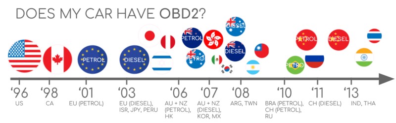
To ascertain if your vehicle is OBD2 compliant, consider these guidelines based on where and when it was originally purchased:
Determining OBD2 Compliance: Guidelines for vehicle owners in EU and US.
These dates serve as a general rule of thumb. For vehicles manufactured around these transition years, it’s always best to consult your vehicle’s owner’s manual or contact the manufacturer to confirm OBD2 compliance. Websites like scantool.net also offer resources to help determine OBD2 compliance based on vehicle details.
A Brief History of OBD2: From Emission Control to Standard Protocol
The story of OBD2 begins in California, driven by the stringent emission control regulations set by the California Air Resources Board (CARB). Starting in 1991, CARB mandated OBD systems in all new vehicles sold in California to monitor and control vehicle emissions.
Building upon this, the Society of Automotive Engineers (SAE) played a pivotal role in standardizing the diagnostic landscape. SAE recommended the OBD2 standard, leading to the standardization of Diagnostic Trouble Codes (DTCs) and the physical OBD connector across different vehicle manufacturers, documented under the SAE J1962 standard.
The OBD2 standard adoption unfolded globally in stages:
- 1996: OBD2 became mandatory in the United States for all cars and light trucks, marking a significant step towards standardized vehicle diagnostics.
- 2001: The European Union followed suit, requiring OBD2 for gasoline cars, expanding its reach beyond North America.
- 2003: The EU extended the mandate to include diesel cars (EOBD – European On-Board Diagnostics), ensuring broader coverage for emission diagnostics.
- 2005: OBD2 requirements in the US expanded to include medium-duty vehicles, further solidifying its role in vehicle diagnostics.
- 2008: A pivotal year for communication protocols, 2008 saw the US mandate ISO 15765-4 (CAN) as the foundation for OBD2 communication, standardizing the communication layer. This standardization also implicitly set the stage for OBD2 baud rate considerations, as CAN bus operates at specific baud rates.
- 2010: Finally, OBD2 compliance became mandatory for heavy-duty vehicles in the US, completing the rollout across all vehicle classes.
OBD2 History: Driven by Emission Control and evolving into a standardized protocol.
OBD2 History Timeline: A visual overview of OBD2 development and standardization milestones.
OBD2 Future: Envisioning OBD3 with remote diagnostics, emissions testing, and cloud integration.
The Future of OBD2: Trends and Innovations
While firmly established, OBD2 is not static. Its future is being shaped by emerging trends, particularly in the realms of electric vehicles, enhanced diagnostic protocols, and connected car technologies.
Originally designed for emission control in combustion engine vehicles, legislated OBD2 has a somewhat ambiguous role in the electric vehicle (EV) landscape. Interestingly, EVs are not inherently required to support OBD2 in the same way combustion engine cars are. This is reflected in the fact that many modern EVs do not support standard OBD2 requests. Instead, they often utilize OEM-specific protocols like UDS (Unified Diagnostic Services) for diagnostics. Decoding data from these EVs often requires reverse engineering efforts, as highlighted in case studies for brands like Tesla, Hyundai/Kia, Nissan, and VW/Skoda.
Recognizing the limitations of current OBD2 implementations in data richness and lower-layer protocols, advancements like WWH-OBD (World Wide Harmonized OBD) and OBDonUDS (OBD on UDS) are emerging. These protocols aim to modernize OBD communication by leveraging the UDS protocol, offering potential improvements in diagnostic capabilities and data accessibility.
The rise of connected cars is also influencing the future of OBD. Traditional OBD2 testing methods can be time-consuming and less efficient in today’s connected world. OBD3, a concept still under development, proposes integrating telematics into vehicles. This envisions vehicles equipped with a radio transponder to wirelessly transmit Vehicle Identification Numbers (VIN) and DTCs to a central server for automated emission checks and diagnostics.
Technologies facilitating wireless OBD2 data transfer already exist, such as WiFi and cellular CAN loggers. However, the prospect of widespread OBD3 implementation raises privacy and surveillance concerns, presenting political and societal challenges.
Another significant trend involves the evolving perception of OBD2 data access. Originally intended for repair shop servicing, OBD2 is now extensively used by third-party services for real-time data acquisition. However, some automotive manufacturers are seeking to restrict this third-party access, arguing that OBD2 was never designed for broad data-driven economies and raising security concerns about potential car hacking. Proposals to limit OBD2 functionality during driving and centralize data collection are being discussed, potentially reshaping the landscape for OBD2-based third-party services and impacting data access in the automotive industry.
OBD2 Future: Electric Vehicles and potential shifts in data access and diagnostic approaches.
Deep Dive: Understanding Baud Rate in OBD2 Communication
In the context of OBD2 and particularly when communicating over CAN bus, baud rate is a critical parameter. It dictates the speed of data transmission, essentially the number of signal changes per second, measured in bits per second (bps). Common OBD2 baud rates are 250 kilobits per second (kbps) and 500 kbps.
Think of baud rate as the tempo of communication. If the baud rate is set incorrectly, it’s like trying to listen to music played at the wrong speed – the message becomes unintelligible. For OBD2 communication, both the diagnostic tool and the vehicle’s ECU must be configured to the same baud rate to ensure successful data exchange.
The selection of OBD2 baud rate is often determined by the vehicle manufacturer and the specific CAN protocol implementation. Factors influencing this choice include:
- Network complexity and data volume: Higher baud rates like 500 kbps are used when there’s a need to transmit larger volumes of data or when the network is more complex, requiring faster communication.
- Electromagnetic compatibility (EMC): Lower baud rates like 250 kbps can sometimes be preferred in environments where electromagnetic interference is a concern, as lower frequencies can be less susceptible to noise.
- Historical and standard practices: The automotive industry has evolved, and earlier CAN implementations might have favored 250 kbps, while newer systems might lean towards 500 kbps for increased bandwidth.
In practical OBD2 diagnostics, especially when using CAN bus, correctly identifying and configuring the OBD2 baud rate is a crucial first step. Many OBD2 scanners and data loggers offer auto-baud rate detection capabilities to simplify this process. However, understanding the concept and potential issues related to baud rate is essential for reliable OBD2 communication. Mismatched baud rates are a common cause of communication errors and can prevent successful diagnostic data retrieval.
Enhance Your OBD2 Expertise: The Ultimate CAN Guide
Ready to become a CAN bus and OBD2 expert?
Download our comprehensive 160+ page PDF guide, featuring 12 simple introductions to CAN bus and related technologies:
Download now
OBD2 Standards: Laying the Foundation for Diagnostics
OBD2 operates as a higher-layer protocol, similar to a language built upon a communication method. CAN bus acts as this communication method, analogous to a telephone line. This hierarchical structure places OBD2 alongside other CAN-based higher-layer protocols like J1939, CANopen, and NMEA 2000, each designed for specific applications but sharing the underlying CAN communication framework.
OBD2 standards meticulously define various aspects of the diagnostic system, including the OBD2 connector, the lower-layer communication protocols, OBD2 Parameter IDs (PIDs), and more. These standards are structured within a 7-layer OSI model framework, providing a layered approach to understanding the complexities of OBD2 communication.
It’s worth noting that the OBD2 standards landscape involves both SAE (primarily US-centric) and ISO (international) standards. Often, SAE and ISO standards address similar aspects of OBD2, with some being technically equivalent, such as SAE J1979 and ISO 15031-5 (diagnostic services) and SAE J1962 and ISO 15031-3 (OBD connector).
OBD2 vs CAN Bus: Illustrating the OSI Model and relevant ISO and SAE standards.
OBD Connector Pinout: Detailed view of the OBD2 connector pin assignments.
The OBD2 Connector: Your Access Point [SAE J1962 / ISO 15031-3]
The 16-pin OBD2 connector, standardized under SAE J1962 and ISO 15031-3, serves as the physical interface for accessing your vehicle’s diagnostic data. This connector, also known as the Data Link Connector (DLC), provides a standardized and readily accessible point for diagnostic tools to interface with the vehicle’s systems.
Key features and considerations of the OBD2 connector include:
- Location: Typically positioned within easy reach of the driver, often under the dashboard near the steering column, although it can sometimes be hidden behind a panel.
- Pin 16: Provides battery power, often remaining active even when the ignition is off, allowing for certain diagnostic functions to be performed without the vehicle running.
- Pinout variation: The specific pinout configuration within the OBD2 connector can vary depending on the communication protocol used by the vehicle.
- CAN bus integration: For vehicles using CAN bus as the communication protocol, pins 6 (CAN-High) and 14 (CAN-Low) are crucial, facilitating the CAN communication link. The OBD2 baud rate for CAN communication is also configured and established via these pins.
OBD2 Connector Types: Type A vs. Type B
In practice, you may encounter two main types of OBD2 connectors: Type A and Type B. Type A is predominantly found in cars and light-duty vehicles, while Type B is more common in medium and heavy-duty vehicles.
While both types share a similar pinout structure, key differences exist:
- Power supply: Type A connectors typically provide 12V power supply, suitable for car electrical systems. Type B connectors are designed for 24V systems commonly found in trucks and heavy vehicles.
- Baud Rate: Often, the default OBD2 baud rate differs between the types. Cars (Type A) commonly use 500 kbps, while heavy-duty vehicles (Type B) often use 250 kbps, with newer systems increasingly supporting 500 kbps as well.
Visually distinguishing between the two types is possible by observing the groove in the connector. Type B connectors have an interrupted groove in the middle, unlike Type A. This physical difference ensures compatibility considerations when selecting OBD2 adapter cables. Type B OBD2 adapter cables are generally compatible with both Type A and Type B sockets, whereas Type A cables may not fit into Type B sockets due to the groove difference.
OBD2 Connector Type A vs B: Illustrating the differences in power supply and typical vehicle applications.
OBD2 vs CAN bus: Highlighting the relationship and ISO 15765 standard.
OBD2 and CAN Bus: Communication Foundation [ISO 15765-4]
Since 2008, CAN bus (Controller Area Network) has become the mandatory lower-layer protocol for OBD2 in all vehicles sold in the US, as mandated by ISO 15765. This standard, ISO 15765-4 (also known as Diagnostics over CAN or DoCAN), defines a specific set of rules and restrictions applied to the fundamental CAN standard (ISO 11898) to ensure interoperability and standardization in automotive diagnostics.
ISO 15765-4 standardizes the CAN interface for diagnostic equipment, focusing on the physical layer, data link layer, and network layer. Key specifications include:
- CAN bus bit-rate (Baud Rate): The standard specifies two permissible OBD2 baud rates for CAN communication: 250 kbps and 500 kbps. Diagnostic tools must be capable of operating at both rates to ensure compatibility with a wide range of vehicles.
- CAN IDs: Both 11-bit (standard CAN) and 29-bit (extended CAN) CAN identifiers are permitted for OBD2 communication, providing flexibility in addressing and message prioritization.
- Specific CAN IDs for OBD: ISO 15765-4 defines reserved CAN IDs specifically for OBD request and response messages, ensuring that diagnostic communication is properly addressed and managed on the CAN network.
- Diagnostic CAN frame data length: OBD2 diagnostic CAN frames are restricted to a maximum data payload length of 8 bytes, adhering to the standard CAN frame structure.
- OBD2 adapter cable length limit: To maintain signal integrity and reliable communication, the OBD2 adapter cable length is limited to a maximum of 5 meters. This helps to minimize signal degradation and potential communication errors, especially at higher OBD2 baud rates.
OBD2 CAN Identifiers: 11-bit and 29-bit Addressing
OBD2 communication over CAN bus relies on a request-response message exchange. Understanding CAN identifiers (IDs) is crucial for deciphering OBD2 communication.
In most passenger cars, 11-bit CAN IDs are predominantly used for OBD2 communication. Here, the ‘Functional Addressing’ ID, 0x7DF, plays a key role. When a diagnostic tool sends a request with CAN ID 0x7DF, it’s essentially a broadcast request, asking all OBD2-compliant ECUs in the vehicle if they have data to report for the requested parameter. This is in line with the ISO 15765-4 standard for functional addressing.
In contrast, CAN IDs in the range of 0x7E0 to 0x7E7 are reserved for ‘Physical Addressing’ requests. These IDs allow the diagnostic tool to directly communicate with a specific ECU, rather than broadcasting a request to all ECUs. Physical addressing is less commonly used for standard OBD2 diagnostics but can be useful for targeting specific modules.
ECUs respond to OBD2 requests using 11-bit CAN IDs in the range of 0x7E8 to 0x7EF. The most frequently encountered response ID is 0x7E8, typically originating from the ECM (Engine Control Module), which is the primary ECU for engine-related parameters. Another common response ID is 0x7E9, often from the TCM (Transmission Control Module).
In some vehicle types, particularly vans and medium/heavy-duty vehicles, extended 29-bit CAN identifiers might be used for OBD2 communication instead of the standard 11-bit IDs.
For 29-bit CAN, the ‘Functional Addressing’ CAN ID is 0x18DB33F1. Similar to the 11-bit functional addressing, this ID broadcasts the request to all relevant ECUs.
Responses in 29-bit CAN OBD2 typically use CAN IDs in the range of 0x18DAF100 to 0x18DAF1FF. Common response IDs include 0x18DAF110 and 0x18DAF11E. These response IDs are sometimes represented in the J1939 PGN (Parameter Group Number) format. Specifically, the PGN 0xDA00 (55808) in J1939-71 is designated as ‘Reserved for ISO 15765-2’, highlighting the interrelation between OBD2 (ISO 15765) and J1939 standards in certain vehicle applications.
OBD2 Request and Response Frames: Illustrating the flow of OBD2 communication and PID data.
OBD2 vs Proprietary CAN bus: Contrasting standardized OBD2 data with OEM-specific CAN data.
OBD2 vs. Proprietary CAN Protocols: Two Parallel Systems
It’s crucial to understand that a vehicle’s Electronic Control Units (ECUs) operate primarily based on OEM-specific CAN protocols, independent of OBD2. Vehicle manufacturers develop their own proprietary CAN communication protocols for the core functions of the vehicle. These protocols are often unique to the vehicle brand, model, and year, and are not publicly documented. Unless you are the OEM and have access to this proprietary information, interpreting this raw CAN data directly can be challenging, typically requiring reverse engineering efforts.
When you connect a CAN bus data logger to your vehicle’s OBD2 connector, you may observe both OEM-specific CAN data traffic and OBD2 communication. OEM-specific CAN data is often broadcast at high frequencies (e.g., 1000-2000 frames/second) and encompasses a wide range of vehicle operation parameters beyond the standardized OBD2 data.
However, in many modern vehicles, a ‘gateway’ module is implemented. This gateway acts as a filter, restricting access to the OEM-specific CAN data via the OBD2 connector. The gateway primarily allows only OBD2 communication through the OBD2 port, effectively isolating the proprietary vehicle network from direct external access via the OBD2 connector.
In essence, OBD2 can be viewed as an additional, higher-layer protocol that operates in parallel to the OEM-specific CAN protocol within the vehicle. It’s a standardized diagnostic interface layered on top of the vehicle’s native communication network.
Baud Rate and ID Validation: Ensuring Correct Communication Parameters
As previously discussed, OBD2 CAN communication can utilize two different baud rates (250 kbps, 500 kbps) and two CAN ID lengths (11-bit, 29-bit). This results in four possible combinations of communication parameters. In contemporary vehicles, 500 kbps baud rate and 11-bit CAN IDs are the most prevalent combination. However, diagnostic tools should systematically validate these parameters to ensure correct communication.
ISO 15765-4 provides recommendations for a systematic initialization sequence to automatically determine the correct combination of baud rate and CAN ID length for a given vehicle. This process, illustrated in the flowchart below, leverages the mandatory support for OBD2 service 0x01 PID 0x00 in OBD2-compliant vehicles. The validation process also relies on detecting CAN error frames, which occur when data is transmitted at an incorrect baud rate.
Newer revisions of ISO 15765-4 acknowledge that vehicles may support OBD communication via OBDonUDS (OBD on Unified Diagnostic Services) rather than the traditional OBDonEDS (OBD on Emission Diagnostic Service). This article primarily focuses on OBD2/OBDonEDS (as per ISO 15031-5/SAE J1979), which is more commonly found in non-EV cars today. WWH-OBD/OBDonUDS (as per ISO 14229, ISO 27145-3/SAE J1979-2) is more prevalent in EU trucks and buses.
To distinguish between OBDonEDS and OBDonUDS, diagnostic tools may perform additional tests, specifically sending UDS requests with 11-bit/29-bit functional address IDs for service 0x22 and data identifier (DID) 0xF810 (protocol identification). Vehicles supporting OBDonUDS are expected to have ECUs that respond to this specific DID.
In practice, OBDonEDS (also known as OBD2, SAE OBD, EOBD, or ISO OBD) is the dominant protocol in most non-electric vehicles currently, while WWH-OBD is primarily implemented in European trucks and buses.
OBD2 Baud Rate and CAN ID Validation: Flowchart illustrating the systematic process for determining communication parameters.
OBD2 Standards: Overview of the five lower-layer OBD2 protocols, including CAN (ISO 15765).
Five Lower-Layer OBD2 Protocols: Beyond CAN
While CAN bus (ISO 15765) is now the dominant lower-layer protocol for OBD2 in the vast majority of vehicles, particularly those manufactured post-2008, it’s important to be aware of the other four lower-layer protocols that were previously used as the foundation for OBD2, especially when working with older vehicles. The OBD2 connector pinout itself can sometimes provide clues about the protocol used in older vehicles.
The five lower-layer OBD2 protocols are:
- ISO 15765 (CAN bus): Mandatory in US vehicles since 2008 and currently the most widely used protocol globally for OBD2 communication. It offers high-speed communication and robust network capabilities, making it well-suited for modern vehicle systems. As discussed, CAN bus communication in OBD2 involves specific baud rates (250 kbps or 500 kbps) and CAN ID configurations.
- ISO 14230-4 (KWP2000): The Keyword Protocol 2000 (KWP2000) was a prevalent protocol, particularly in vehicles manufactured around 2003 and later, especially in Asian markets. It’s a slower protocol compared to CAN but was widely adopted during its time.
- ISO 9141-2: This protocol was used in European, Chrysler, and Asian vehicles manufactured roughly between 2000 and 2004. It’s another serial communication protocol, predating the widespread adoption of CAN bus in OBD2.
- SAE J1850 (VPW – Variable Pulse Width Modulation): SAE J1850 VPW was primarily used in older General Motors (GM) vehicles. It utilizes a variable pulse width modulation scheme for data transmission.
- SAE J1850 (PWM – Pulse Width Modulation): SAE J1850 PWM was mainly employed in older Ford vehicles. Similar to VPW, it uses pulse width modulation but with a different modulation scheme.
ISO-TP: Transporting OBD2 Messages [ISO 15765-2]
All OBD2 data communication over CAN bus relies on a transport protocol called ISO-TP (ISO 15765-2). ISO-TP is essential because it enables the transmission of OBD2 messages with payloads exceeding the 8-byte limit of a standard CAN frame. This capability is necessary for certain OBD2 functionalities, such as retrieving the Vehicle Identification Number (VIN) or Diagnostic Trouble Codes (DTCs), which often require more than 8 bytes of data.
ISO-TP provides mechanisms for segmentation, flow control, and reassembly of larger messages that are broken down into multiple CAN frames. For a deeper understanding of transport protocols and flow control, refer to introductions to UDS (Unified Diagnostic Services).
However, a significant portion of OBD2 data, particularly real-time parameter requests, can fit within a single CAN frame. In these cases, ISO 15765-2 specifies the use of ‘Single Frame’ (SF) messages. In a Single Frame message, the first data byte (known as the PCI field – Protocol Control Information) indicates the payload length (excluding padding). This leaves 7 bytes within the CAN frame’s data field available for OBD2-related communication.
ISO 15765-2 ISO-TP OBD2 Frame Types: Illustrating Single Frame, First Frame, Consecutive Frame, and Flow Control frame types.
The OBD2 Diagnostic Message: Structure and Components [SAE J1979, ISO 15031-5]
To effectively work with OBD2 data over CAN, understanding the structure of an OBD2 diagnostic message is crucial. When examining a raw ‘Single Frame’ OBD2 CAN message, it can be conceptually broken down into these key components:
- CAN Identifier: As previously discussed, this identifies the message’s source and destination, e.g., 0x7DF for functional requests, 0x7E8 for ECM responses.
- Data Length (PCI Field): The first byte of the CAN data payload, as defined by ISO-TP. For Single Frame messages, it indicates the length of the OBD2 payload (modes, PIDs, data bytes).
- OBD2 Payload: The remaining bytes in the CAN data payload (up to 7 bytes in Single Frame messages) contain the actual OBD2 diagnostic information, structured as:
- Mode (Service): Specifies the OBD2 diagnostic service being requested or responded to (e.g., 0x01 for showing current data).
- Parameter ID (PID): Identifies the specific parameter being requested or reported within a given mode (e.g., 0x0D for vehicle speed).
- Data Bytes: Contain the actual data values for the requested parameter, encoded according to OBD2 specifications.
OBD2 PIDs Message Structure: Breakdown of an OBD2 message, showing Mode, PID, and Data Bytes.
Example: OBD2 Request and Response for Vehicle Speed
Let’s illustrate the OBD2 message structure with a practical example: requesting and receiving vehicle speed data.
In this scenario, an external diagnostic tool initiates a request to the vehicle to obtain the current vehicle speed. The request message is structured as follows:
- CAN ID: 0x7DF (Functional Addressing – request to all OBD2 ECUs)
- Payload (Data Bytes):
- Byte 1 (PCI): 0x02 (indicating a Single Frame message with 2 bytes of OBD2 payload)
- Byte 2 (Mode): 0x01 (Service 01: Show current data)
- Byte 3 (PID): 0x0D (Parameter ID 0x0D: Vehicle Speed)
Upon receiving this request, the vehicle’s ECU (typically the ECM) processes it and responds with a message containing the vehicle speed data:
- CAN ID: 0x7E8 (Response from ECM)
- Payload (Data Bytes):
- Byte 1 (PCI): 0x03 (Single Frame with 3 bytes of OBD2 payload)
- Byte 2 (Mode + 0x40): 0x41 (Response to Service 01, mode value is 0x01 + 0x40 = 0x41)
- Byte 3 (PID): 0x0D (Echoing the requested PID 0x0D)
- Byte 4 (Data Byte): 0x32 (Vehicle Speed Value – hexadecimal representation)
To interpret the vehicle speed value, we need to refer to the OBD2 PID specifications for PID 0x0D. These specifications define the scaling and units for each PID. For PID 0x0D (Vehicle Speed), the value is typically in km/h, and each unit increment in the data byte corresponds to 1 km/h. In our example, the data byte value is 0x32 in hexadecimal, which is 50 in decimal. Therefore, the decoded vehicle speed is 50 km/h.
OBD2 Request 7DF and Response 7E8: Example of OBD2 communication for requesting vehicle speed.
OBD2 PID Example: Vehicle Speed (PID 0D) and its data representation.
OBD2 Services (Modes): Overview of the 10 standardized OBD2 diagnostic services/modes.
The 10 OBD2 Services (Modes): Diagnostic Functionalities
OBD2 defines 10 standardized diagnostic services, also commonly referred to as modes. Each mode corresponds to a specific category of diagnostic function. These modes are accessed by sending a request message with the corresponding mode code in the second byte of the OBD2 payload.
The 10 standard OBD2 services/modes are:
- Mode 0x01: Show current data: Provides access to real-time vehicle parameters, such as engine speed (RPM), vehicle speed, coolant temperature, oxygen sensor readings, and many more. This mode is used for monitoring live data and vehicle operating conditions.
- Mode 0x02: Show freeze frame data: Displays diagnostic data that was captured and stored when a Diagnostic Trouble Code (DTC) was set. Freeze frame data provides a snapshot of the vehicle’s condition at the moment a fault was detected.
- Mode 0x03: Show stored Diagnostic Trouble Codes (DTCs): Retrieves a list of currently active, emissions-related DTCs that are stored in the vehicle’s ECU memory.
- Mode 0x04: Clear Diagnostic Trouble Codes (DTCs) and stored values: Clears active DTCs and resets certain stored values in the ECU. This mode should be used with caution and understanding of its implications.
- Mode 0x05: Test results, oxygen sensor monitoring (non-CAN): Provides results from on-board oxygen sensor monitoring tests. This mode is primarily for non-CAN based OBD2 implementations.
- Mode 0x06: Test results, other component/system monitoring (non-CAN): Similar to mode 0x05, but for monitoring tests of other components and systems. Primarily for non-CAN OBD2.
- Mode 0x07: Show pending DTCs (detected during current or last driving cycle): Displays DTCs that are considered “pending.” These are DTCs detected during the current or last driving cycle but haven’t yet matured into active DTCs.
- Mode 0x08: Control operation of on-board component/system: Allows for bi-directional control of certain on-board components or systems for diagnostic purposes. This mode is less commonly implemented and usage varies.
- Mode 0x09: Request vehicle information: Provides access to vehicle-specific information, such as the Vehicle Identification Number (VIN), calibration IDs, and component IDs.
- Mode 0x0A (0x0A): Show permanent DTCs: Retrieves “permanent” DTCs, which are DTCs that cannot be cleared by simply using mode 0x04. They typically require the underlying fault to be resolved and the vehicle to undergo specific drive cycles to clear.
It’s important to note that vehicles are not required to support all 10 OBD2 modes. The level of mode support can vary between manufacturers and vehicle models. Additionally, vehicle manufacturers may implement OEM-specific OBD2 modes beyond the 10 standardized modes to provide access to more detailed diagnostic or control functionalities.
In OBD2 messages, the mode code is placed in the second byte of the payload. In a request message, the mode code is used directly (e.g., 0x01 for mode 01). In a response message, 0x40 is added to the requested mode code (e.g., a response to a mode 0x01 request will have a mode byte of 0x41).
OBD2 Parameter IDs (PIDs): Accessing Specific Data Points
Within each OBD2 mode, Parameter IDs (PIDs) are used to specify the particular data point or parameter being requested or reported. Mode 0x01 (Show current data) is particularly rich in PIDs, containing approximately 200 standardized PIDs that provide access to a wide array of real-time vehicle data, including speed, RPM, fuel level, temperatures, pressures, and emission-related parameters.
However, it’s crucial to understand that vehicles are not obligated to support all standardized OBD2 PIDs within a given mode. In practice, most vehicles only support a subset of the available PIDs. The specific PIDs supported by a vehicle depend on the manufacturer, model, and year.
One PID holds a special significance: PID 0x00 within Mode 0x01. If an emissions-related ECU in a vehicle supports any OBD2 services, it must support mode 0x01 PID 0x00. When a diagnostic tool requests mode 0x01 PID 0x00, the vehicle’s ECU responds by indicating which PIDs in the range of 0x01 to 0x20 it supports. This makes PID 0x00 a fundamental tool for OBD2 compatibility testing and for discovering the supported PIDs on a vehicle.
Furthermore, PIDs 0x20, 0x40, 0x60, 0x80, 0xA0, and 0xC0 in mode 0x01 serve a similar purpose. By querying these PIDs, a diagnostic tool can progressively determine the vehicle’s support for the remaining PIDs within mode 0x01, covering ranges 0x21-0x40, 0x41-0x60, and so on, up to 0xC1-0xE0.
OBD2 Request and Response Frames: Reiterating the structure of OBD2 communication and PID data.
OBD2 PID Overview Tool: Example interface of an OBD2 PID lookup and interpretation tool.
Tip: Utilizing an OBD2 PID Overview Tool
The appendices of SAE J1979 and ISO 15031-5 standards documents contain detailed scaling and unit information for standardized OBD2 PIDs. This information is essential for correctly decoding the raw data bytes received from the vehicle into meaningful physical values (e.g., converting raw byte values into km/h, degrees Celsius, etc.).
To simplify the process of working with mode 0x01 PIDs, consider using an OBD2 PID overview tool. These tools provide a user-friendly interface to look up PID definitions, construct OBD2 request frames, and dynamically decode OBD2 responses. Our OBD2 PID overview tool is a valuable resource for this purpose.
OBD2 PID overview tool
Link to the OBD2 PID Overview Tool for easy PID lookup and interpretation.
Practical OBD2 Data Logging and Decoding
Let’s explore a practical example of how to log OBD2 data using a CAN bus data logger like the CANedge. The CANedge is configurable to transmit custom CAN frames, making it suitable for sending OBD2 requests and logging the responses.
To begin, connect the CANedge to your vehicle’s OBD2 port using an OBD2-DB9 adapter cable.
OBD2 PID Data Logger: Illustration of an OBD2 data logger requesting PID data.
OBD2 Baud Rate Test: Validating the OBD2 baud rate for successful communication.
OBD2 Supported PIDs Test: Reviewing responses to ‘Supported PIDs’ requests in asammdf.
Step #1: Baud Rate, ID, and Supported PID Validation
As outlined in ISO 15765-4, the first step is to determine the correct OBD2 baud rate, CAN IDs, and supported PIDs for the target vehicle. The CANedge, like many professional diagnostic tools, can be configured to perform these validation steps. Refer to the CANedge Intro documentation for detailed configuration instructions.
The validation process typically involves these steps:
- Baud Rate Test: Attempt to send a CAN frame at a default baud rate, such as 500 kbps. Monitor for successful transmission. If transmission fails (indicated by CAN error frames), repeat the test at an alternative baud rate, such as 250 kbps.
- Bit-rate Identification: Based on the successful transmission, identify the correct OBD2 baud rate used by the vehicle.
- Supported PIDs Request: Send multiple ‘Supported PIDs’ requests (Mode 0x01 PID 0x00, 0x20, 0x40, etc.) to query the vehicle’s ECU for supported PIDs.
- Response Review: Analyze the responses received from the vehicle’s ECU. The response CAN IDs (e.g., 0x7E8, 0x7E9) will indicate whether 11-bit or 29-bit CAN IDs are used for responses. The data bytes in the responses will reveal the ranges of PIDs supported by the vehicle.
- PID Support Determination: Use an OBD2 PID lookup tool to decode the ‘Supported PIDs’ response data and determine the specific PIDs supported by the vehicle.
Pre-configured CANedge configurations are often available to automate these validation tests, simplifying the initial setup.
In most non-electric vehicles manufactured after 2008, you can typically expect to find support for 40-80 PIDs, communicating at a baud rate of 500 kbps, using 11-bit CAN IDs, and following the OBD2/OBDonEDS protocol.
As illustrated in the asammdf GUI screenshot, you might observe multiple responses to a single OBD2 request, particularly for PID 0x00. This is because functional addressing (using request ID 0x7DF) polls all OBD2-compliant ECUs for a response. Since all compliant ECUs must support service 0x01 PID 0x00, multiple responses are common for this PID. For subsequent ‘Supported PIDs’ requests (0x20, 0x40, etc.), you’ll generally see fewer ECUs responding as PID support becomes less universal across modules.
Notice that in the example, the ECM ECU (0x7E8) appears to support all the PIDs supported by other ECUs. In such cases, to reduce CAN bus load and potentially improve data acquisition efficiency, you could switch to ‘Physical Addressing’ (using request CAN IDs 0x7E0-0x7E7) and specifically target the ECM (0x7E0) for subsequent PID requests.
Step #2: Configuring OBD2 PID Requests for Logging
Once you’ve validated the OBD2 baud rate, CAN IDs, and identified the PIDs supported by your vehicle, the next step is to configure your data logger (e.g., CANedge) to transmit requests for the specific PIDs you want to log.
Consider these factors when configuring your PID requests:
- CAN ID Selection: For efficient logging, switch to ‘Physical Addressing’ request IDs (e.g., 0x7E0 for ECM) to avoid receiving redundant responses from multiple ECUs for each PID request.
- Request Spacing: Introduce a delay of 300-500 milliseconds between consecutive OBD2 requests. Overly rapid requests (spamming the ECUs) can sometimes cause ECUs to become unresponsive or lead to communication errors.
- Battery Drain Management: Implement triggers in your data logger configuration to stop transmitting OBD2 requests when the vehicle is inactive (e.g., ignition off). This prevents unnecessary battery drain by avoiding ‘waking up’ ECUs when the vehicle is parked.
- Data Filtering: Configure filters in your data logger to record only the relevant OBD2 response messages (e.g., CAN IDs 0x7E8-0x7EF). This is particularly useful if your vehicle also transmits OEM-specific CAN data on the OBD2 port, allowing you to isolate and focus on the OBD2 diagnostic data.
With these configurations in place, your data logger is ready to record raw OBD2 data from your vehicle.
OBD2 Transmit List Example: A sample configuration list of CANedge OBD2 PID requests.
OBD2 Data Decoded: Visual plot of decoded OBD2 data in asammdf, using a DBC file.
Step #3: DBC Decoding of Raw OBD2 Data
To effectively analyze and visualize the logged raw OBD2 data, you need to decode it into human-readable ‘physical values’ (e.g., km/h, °C, RPM). This decoding process involves converting the raw byte values into engineering units based on the scaling and offset factors defined in the OBD2 PID specifications.
The necessary decoding information is documented in ISO 15031-5/SAE J1979 standards and is often summarized in online resources like Wikipedia. To simplify the decoding process, a free OBD2 DBC file is available. DBC (CAN database) files are widely used in CAN bus analysis software to define message structures and signal decoding rules. Using an OBD2 DBC file allows you to readily decode raw OBD2 data in most CAN bus software tools that support DBC import and decoding.
Decoding OBD2 data is slightly more complex than decoding typical CAN signals. This is because multiple OBD2 PIDs are transmitted using the same CAN ID (e.g., 0x7E8). Therefore, the CAN ID alone is not sufficient to uniquely identify the signal encoded in the payload.
To address this, OBD2 decoding requires considering not only the CAN ID but also the OBD2 mode and the specific OBD2 PID within the message payload. This technique is known as ‘extended multiplexing‘. DBC files can be designed to handle extended multiplexing, allowing software tools to correctly interpret OBD2 data by considering the combination of CAN ID, mode, and PID.
CANedge: Your Dedicated OBD2 Data Logger
The CANedge is a robust and user-friendly solution for recording OBD2 data. It logs data directly to an 8-32 GB SD card, providing ample storage for extended logging sessions. Simply connect the CANedge to your vehicle’s OBD2 port, configure your desired PIDs and baud rate, and start logging. The recorded data can then be easily decoded and analyzed using free software tools, APIs, and the provided OBD2 DBC file.
OBD2 logger intro
Link to OBD2 Data Logger Introduction for more information about OBD2 logging solutions.
CANedge
Link to CANedge product page for details about the CANedge OBD2 data logger.
OBD2 Multi-Frame Examples: Handling Larger Data Payloads [ISO-TP]
While many OBD2 data exchanges utilize single-frame messages, some diagnostic requests and responses require multi-frame communication to handle larger data payloads. As previously mentioned, ISO-TP (ISO 15765-2) governs multi-frame communication in OBD2.
Multi-frame OBD2 communication involves flow control frames to manage the segmentation and reassembly of messages spanning multiple CAN frames. In practice, a common approach is to transmit a static flow control frame approximately 50 milliseconds after the initial request frame, as demonstrated in the CANedge configuration examples.
Processing multi-frame OBD2 responses necessitates CAN software or API tools that support ISO-TP protocol handling. Tools like the CANedge MF4 decoders are designed to correctly decode multi-frame OBD2 data.
OBD2 Multi-Frame Request: Example of a multi-frame request message for Vehicle Identification Number (VIN).
Example 1: Retrieving the Vehicle Identification Number (VIN) via OBD2
The Vehicle Identification Number (VIN) is a critical piece of vehicle information used in telematics, diagnostics, and various other automotive applications. OBD2 mode 0x09 PID 0x02 is used to request the VIN from a vehicle.
The process for retrieving the VIN involves:
-
Request Message: The diagnostic tool sends a Single Frame request with:
- PCI field: 0x02
- Request service identifier (Mode): 0x09
- PID: 0x02 (PID for VIN request)
-
Response – First Frame: The vehicle responds with a First Frame message indicating a multi-frame response. The First Frame contains:
- PCI: First Frame indicator
- Length: 0x014 (20 bytes – total length of the VIN response)
- Mode: 0x49 (Response to mode 0x09)
- PID: 0x02 (Echoing the requested PID)
- NODI (Number Of Data Items): 0x01 (indicating one VIN is being returned)
- VIN Data: The remaining 17 bytes of the First Frame and subsequent Consecutive Frames contain the VIN characters encoded in hexadecimal ASCII representation.
The VIN data bytes need to be converted from HEX to ASCII to obtain the human-readable VIN string.
Example 2: Multi-PID Request (Requesting 6 PIDs in One Request)
OBD2 allows diagnostic tools to request up to 6 mode 0x01 PIDs in a single request frame. The ECU is expected to respond with data for the supported PIDs from the request (omitting data for unsupported PIDs), potentially using multi-frame responses if the data exceeds a single CAN frame.
This multi-PID request feature can improve data acquisition efficiency by reducing the number of request messages. However, it also introduces complexities in data decoding, particularly if using generic OBD2 DBC files. The signal encoding becomes dependent on the specific PIDs requested and their order in the request.
While technically feasible, using multi-PID requests for general OBD2 data logging is generally not recommended due to the decoding complexities and reduced DBC file reusability across different vehicles or request configurations.
The multi-frame response to a multi-PID request is similar in structure to the VIN response but includes the requested PIDs as well as their corresponding data values within the payload. The PIDs in the response are often (but not always) ordered in the same sequence as they were requested.
Decoding multi-PID responses using standard DBC files becomes challenging because the DBC file would need to account for the specific payload position of each PID, which can vary based on the requested PIDs and vehicle implementation. This makes it difficult to create generic DBC files that work consistently across different vehicles and multi-PID request combinations.
While custom scripts and advanced data processing techniques can be employed to handle multi-PID responses by correlating response messages with the corresponding request messages, this approach adds complexity and may not be scalable for large-scale data analysis or diverse vehicle environments.
Example 3: Retrieving Diagnostic Trouble Codes (DTCs)
OBD2 mode 0x03 (‘Show stored Diagnostic Trouble Codes’) is used to retrieve emissions-related Diagnostic Trouble Codes (DTCs) from the vehicle’s ECU. The request message for mode 0x03 does not include a PID.
The ECU responds with the number of DTCs currently stored (which could be zero if no DTCs are active). Each DTC is represented by 2 data bytes. If more than 2 DTCs are stored, multi-frame responses are necessary to transmit all the DTC data.
The 2-byte DTC value is structured according to ISO 15031-5/ISO 15031-6. The first 2 bits of the first byte define the DTC ‘category’ (e.g., Powertrain, Chassis, Body, Network), while the remaining 14 bits form a 4-digit code (displayed in hexadecimal). OBD2 DTC lookup tools, such as repairpal.com, can be used to decode the 4-digit DTC code and obtain a textual description of the fault.
OBD2 DTC Decoding: Example of DTC data structure and decoding process.
In the example trace, a request for mode 0x03 is sent, and the ECU responds with a multi-frame message indicating 6 DTCs are stored. The subsequent frames contain the 2-byte DTC codes, which can then be decoded using a DTC lookup tool to identify the specific faults.
OBD2 Data Logging Use Cases: Applications Across Industries
OBD2 data logging has a wide range of applications across various industries, leveraging the wealth of vehicle data available through the standardized OBD2 interface.
OBD2 Data Logger Applications: Illustrating diverse use cases for OBD2 data logging.
Vehicle Data Logging for Cars and Light Trucks
OBD2 data logging in cars and light trucks offers valuable insights for various purposes:
- Fuel Efficiency Optimization: Analyzing OBD2 parameters like fuel consumption, engine load, and speed can help drivers and fleet managers identify areas for improving driving habits and reducing fuel costs.
- Driving Behavior Analysis: OBD2 data provides detailed information about driving patterns, acceleration, braking, and speed profiles. This data can be used for driver training, insurance risk assessment, and developing eco-driving strategies.
- Prototype Testing and Validation: Automotive engineers and component manufacturers use OBD2 data logging to validate the performance and integration of new prototype parts, software updates, or vehicle systems under real-world driving conditions.
- Insurance Telematics: OBD2 data loggers are used in usage-based insurance (UBI) programs to track mileage, driving behavior, and vehicle health, enabling personalized insurance premiums based on actual vehicle usage and driving risk.
obd2 logger
Link to OBD2 Data Logger Solutions for car and light truck applications.
OBD2 Real-Time Streaming: Enabling real-time diagnostics and data visualization.
Real-Time Vehicle Diagnostics and Monitoring
OBD2 interfaces and real-time data streaming capabilities are crucial for:
- Vehicle Diagnostics and Repair: Mechanics and technicians use OBD2 scanners and interfaces to stream real-time OBD2 data for diagnosing vehicle issues, troubleshooting fault codes, and monitoring engine performance during repairs.
- Performance Monitoring and Tuning: Car enthusiasts and performance tuners utilize real-time OBD2 data to monitor engine parameters, optimize vehicle performance, and fine-tune engine control systems.
- Custom Dashboards and Displays: Real-time OBD2 data can be streamed to custom dashboards and displays, providing drivers with live information about vehicle performance, engine parameters, and fuel efficiency.
obd2 streaming
Link to OBD2 Streaming Solutions for real-time data access and diagnostics.
OBD2 Predictive Maintenance: Leveraging OBD2 data for predictive maintenance and vehicle health monitoring.
Predictive Maintenance and Vehicle Health Monitoring
Integrating OBD2 data logging with IoT (Internet of Things) technologies enables:
- Predictive Maintenance: Cloud-connected OBD2 loggers can continuously monitor vehicle health parameters and detect early warning signs of potential failures. This allows for proactive maintenance scheduling, reducing downtime and repair costs.
- Fleet Management and Telematics: OBD2 data streamed to the cloud provides fleet managers with real-time insights into vehicle locations, engine health, driving behavior, and fuel consumption, enabling optimized fleet operations and maintenance scheduling.
- Remote Diagnostics and Assistance: OBD2 data can be remotely accessed by service centers or vehicle manufacturers to diagnose vehicle issues remotely, provide over-the-air software updates, and offer proactive customer support.
predictive maintenance
Link to Predictive Maintenance Solutions using OBD2 and IoT connectivity.
OBD2 Black Box Logger: Utilizing OBD2 data logging for vehicle black box and event recording applications.
Vehicle Black Box and Event Recording
OBD2 data loggers can serve as ‘black box’ recorders for vehicles and equipment, providing valuable data for:
- Accident Reconstruction and Analysis: In the event of accidents or incidents, OBD2 data loggers can provide objective data about vehicle speed, braking, acceleration, and other parameters leading up to and during the event, aiding in accident reconstruction and liability assessment.
- Warranty and Dispute Resolution: OBD2 data logs can provide verifiable records of vehicle operation, mileage, and engine parameters, which can be valuable in warranty claims, usage disputes, or equipment malfunction investigations.
- Vehicle Usage Monitoring and Accountability: For shared vehicle fleets or equipment rentals, OBD2 data logging can track vehicle usage, operating hours, and potential misuse, ensuring accountability and proper vehicle management.
can bus blackbox
Link to Black Box Data Logging Solutions using CAN bus and OBD2.
Do you have a specific OBD2 data logging use case in mind? Reach out to us for free consultation and expert guidance!
Contact us
Link to Contact Page for inquiries and support.
Explore our comprehensive guides section for more in-depth introductions to CAN bus and related technologies or download our ‘Ultimate Guide’ PDF for a complete resource.
Need to log or stream OBD2 data for your application?
Get your OBD2 data logger today!
Buy now
Link to Product Purchase Page for OBD2 data loggers and hardware.
Contact us
Link to Contact Page for inquiries and support.
Recommended Resources
OBD2 DATA LOGGER: EASILY LOG & CONVERT OBD2 DATA
Link to OBD2 Data Logger Product Page.
CANEDGE2 – PRO CAN IoT LOGGER
Link to CANedge2 Product Page.
CAN BUS INTERFACE: STREAMING OBD2 DATA WITH SAVVYCAN
Link to CAN Bus Interface Product Page.