Are you looking to dive into the world of automotive diagnostics and need to wire your own OBD2 connector? Whether you’re building a custom interface, replacing a damaged connector, or setting up a dedicated diagnostic station, understanding Obd2 Connector Wiring is essential. This guide provides a step-by-step approach to wiring an OBD2 connector, ensuring you can access your vehicle’s data safely and effectively.
Disclaimer: While this guide aims to provide clear instructions, working with automotive electrical systems requires caution. This DIY project is undertaken at your own risk. Incorrect wiring can potentially damage your vehicle’s electronic control unit (ECU) or other components. We are not responsible for any issues that may arise from following these instructions. If you are unsure at any point, consult with a professional automotive technician.
Tools and Parts You’ll Need
Before you begin, gather the necessary tools and parts to ensure a smooth wiring process.
- Wire Strippers/Cutters: For preparing the wires for connection.
- Needle-Nose Pliers: Helpful for manipulating small wires and connector pins.
- Crimping Tool (Molex Crimping Tool Recommended): For securely attaching pins to wires. While a specialized Molex crimping tool is recommended for optimal results, needle-nose pliers can be used with careful technique.
- Soldering Iron (Optional but Recommended): Soldering provides a more robust and reliable connection, especially for finer gauge wires.
- 4-Pin Connector: This connector will interface with your OBD2 cable. Ensure it’s compatible with your wire gauge (22-16AWG) and insulation size (1.3-1.7mm). A suitable option can be found at Corsa Technic 4-Pin Connector.
- OBD-II Cable: This cable provides the OBD2 connector interface. A compatible cable is available at Corsa Technic OBD-II Cable.
Alternative Parts Consideration: If you have spare automotive wire available, you can purchase just the female OBD-II connector and run individual wires to your 4-pin connector. This can be more cost-effective if you already have wire on hand. However, ensure you select the correct 4-pin connector pins that match your wire gauge.
Understanding OBD2 Connector Pinout for Wiring
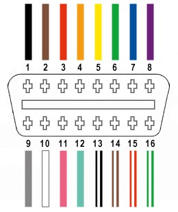
The OBD2 connector has 16 pins, but for basic CAN bus diagnostics, we primarily utilize four key pins. These pins are crucial for establishing communication with your vehicle’s diagnostic system.
- Pin 4 (Chassis Ground): Provides the ground reference for the diagnostic system. (Typically an orange wire in the specified OBD2 cable – OBD2C).
- Pin 6 (CAN High (J-2284)): Carries the CAN bus high signal for communication. (Typically a green wire in OBD2C).
- Pin 14 (CAN Low (J-2284)): Carries the CAN bus low signal for communication. (Typically a brown wire with a white stripe in OBD2C).
- Pin 16 (Battery Power): Provides power to the OBD2 interface. (Typically a green wire with a white stripe in OBD2C).
It’s important to note these color codes are based on the linked OBD2 cable and may vary in other cables. Always verify pin numbers against the OBD2 standard and the wiring diagram of your specific cable.
Step-by-Step OBD2 Connector Wiring Guide
Follow these steps to wire your OBD2 connector effectively.
Step 1: Prepare the OBD2 Cable Wires
Begin by preparing the OBD2 cable. Carefully remove the outer sheath and shielding from the end of the OBD2 cable to expose the individual wires. Identify the four wires you will be using: Pin 4 (Ground), Pin 6 (CAN High), Pin 14 (CAN Low), and Pin 16 (Power). Separate these four wires from the remaining wires and neatly secure the unused wires to keep them out of the way. Zip ties can be helpful for this.
Step 2: Prepare the Wire Ends for the 4-Pin Connector
The wires in the specified OBD2 cable are 26AWG, which is finer than the 22AWG-16AWG pin size of the 4-pin connector. To ensure a secure connection, we need to slightly thicken the wire ends. The wires come pre-stripped with a small amount of exposed wire. Carefully strip off a little more insulation, exposing approximately 3/8″ of wire. Fold the exposed wire back onto itself and twist the strands together to increase the wire thickness, making it a better fit for the 4-pin connector pins. Slide a rubber seal (included with the 4-pin connector kit) onto each of the four prepared wires.
Step 3: Insert Wire into 4-Pin Connector Pins
Take a pin from the 4-pin connector kit. You’ll notice two sets of prongs on the pin. The front prongs are designed to crimp onto the exposed wire, while the rear prongs crimp onto the wire insulation (rubber seal). Insert the prepared wire end into the front of the pin, ensuring the exposed wire is positioned correctly between the front prongs. Use needle-nose pliers to hold the wire in place during the next step, as the 26AWG wire is quite thin compared to the pin.
Step 4: Soldering the Wire to the Pin (Recommended)
Soldering the wire to the pin provides a strong and electrically sound connection. If you choose to solder, carefully apply solder to the area where the wire meets the pin. Ensure the solder flows smoothly and creates a solid bond. If you are new to soldering, practice on scrap wire first. This YouTube video offers helpful soldering tips.
Step 5: Crimping the Front Prongs (Alternative to Soldering)
If you don’t have a soldering iron or prefer not to solder, you can crimp the front prongs of the pin onto the wire. Ideally, use a Molex crimping tool for this step for a professional crimp. If using needle-nose pliers, carefully and gradually fold one prong over the wire using angled pressure. Repeat for the other prong, ensuring a secure grip on the wire. This video demonstrates crimping techniques with pliers. For added security, you can gently squeeze the prongs further with pliers.
Step 6: Crimp the Rear Prongs onto the Seal
Slide the rubber seal up the wire until it sits between the rear prongs of the connector pin. Use the same crimping technique as in Step 5 (either with a crimping tool or needle-nose pliers) to fold the rear prongs over the rubber seal. This secures the seal and provides strain relief for the wire.
Step 7: Wire Pairing (Recommended for Signal Integrity)
While not strictly mandatory, it’s recommended to twist pairs of wires together. This practice, common in data communication wiring, can help reduce electromagnetic interference and improve signal integrity, particularly for CAN bus communication. Pair and twist the wires as follows:
- Pin 4 (Orange – Ground) / Pin 16 (Green w/ White Stripe – Power)
- Pin 6 (Green – CAN High) / Pin 14 (Brown w/ White Stripe – CAN Low)
Step 8: Insert Pins into the 4-Pin Connector Housing
Insert the completed pins into the 4-pin connector housing (4PC) in the correct orientation. Refer to the diagram below for the correct pin assignments:
- Connector Slot A: Pin 14 (Brown w/ White Stripe – CAN Low)
- Connector Slot B: Pin 6 (Green – CAN High)
- Connector Slot C: Pin 16 (Green w/ White Stripe – Power)
- Connector Slot D: Pin 4 (Orange – Ground)
Push each pin into the rear of the connector housing until you hear a click, indicating it is securely locked in place. Needle-nose pliers can assist in gently pulling the wire from the front to ensure the pin is fully seated and locked.
Testing Your OBD2 Connector Wiring
Congratulations! Your OBD2 connector wiring is now complete.
To ensure everything is working correctly, test your newly wired OBD2 connector with a compatible OBD2 scanner on your vehicle.
By following these steps, you can confidently create your own OBD2 connector wiring for automotive diagnostics. Remember to always double-check your connections and exercise caution when working with automotive electrical systems. If you encounter any issues or have further questions, consult with a qualified automotive professional.