Need a simple, practical introduction to Obd2 Diagnostic Cables?
In this guide, we’ll demystify the world of On-Board Diagnostics (OBD2) and focus specifically on the crucial role of the OBD2 diagnostic cable. We’ll cover everything from the OBD2 connector and protocol to how diagnostic cables enable communication with your vehicle’s computer for troubleshooting and performance monitoring.
Note: This is a practical guide, so you’ll learn about selecting the right OBD2 diagnostic cable, understanding its uses, and gaining insights into your car’s health.
Discover why this is becoming a go-to resource for understanding OBD2 diagnostic cables.
You can also explore OBD2 through videos and further resources online.
What is OBD2 and Why Do You Need a Diagnostic Cable?
OBD2 is your car’s built-in self-diagnostic system. It’s a standardized protocol that allows mechanics and car owners to access diagnostic trouble codes (DTCs) and real-time data via a physical connection – this is where the OBD2 diagnostic cable comes in.
You’re likely already familiar with OBD2 in some way:
Ever seen the check engine light or malfunction indicator light on your dashboard?
That’s your car signaling a potential problem. When you take your vehicle to a repair shop, a technician uses an OBD2 scanner connected via an OBD2 diagnostic cable to pinpoint the issue.
They plug the OBD2 reader into the OBD2 16-pin connector, usually located near the steering wheel. The tool, through the OBD2 diagnostic cable, sends ‘OBD2 requests’ to the car’s computer. The car responds with ‘OBD2 responses’ containing information like speed, fuel level, or Diagnostic Trouble Codes (DTCs). This process, facilitated by the OBD2 diagnostic cable, significantly speeds up troubleshooting and repair.
Alt text: OBD2 system displaying malfunction indicator light on a car dashboard, indicating the need for diagnostics using an OBD2 diagnostic cable and scanner.
Is My Car OBD2 Compatible and What Cable Do I Need?
In short: Most likely, yes!
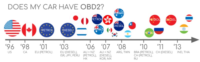
Almost all modern non-electric cars are OBD2 compliant, and many use the CAN bus communication protocol. For older vehicles, even if a 16-pin OBD2 connector is present, it might not actually support the OBD2 protocol. Compliance often depends on where and when the car was originally sold:
Alt text: Chart showing OBD2 compliance by region and vehicle type, helping users determine if their car needs an OBD2 diagnostic cable.
To use OBD2 diagnostics, you’ll need an OBD2 diagnostic cable compatible with your chosen scan tool or interface. Cables come in various types, often with a 16-pin OBD2 connector on one end and a different connector type (like USB, DB9, or Bluetooth) on the other end to connect to your computer, phone, or dedicated scanner.
A Brief History of OBD2 and its Evolution
OBD2’s story begins in California. The California Air Resources Board (CARB) mandated OBD for all new cars from 1991 onwards to monitor emissions.
The OBD2 standard was refined by the Society of Automotive Engineers (SAE), standardizing DTCs and the physical OBD connector across different car manufacturers (SAE J1962). This standardization is critical because it ensures that a universal OBD2 diagnostic cable can be used across compliant vehicles.
The OBD2 standard was progressively implemented worldwide:
- 1996: OBD2 became mandatory in the USA for cars and light trucks.
- 2001: Required in the EU for gasoline cars.
- 2003: Required in the EU for diesel cars as well (EOBD).
- 2005: OBD2 was required in the US for medium-duty vehicles.
- 2008: US cars were mandated to use ISO 15765-4 (CAN) as the foundation for OBD2 communication.
- 2010: OBD2 became mandatory for heavy-duty vehicles in the US.
Alt text: Diagram illustrating the history of OBD2 development and its connection to emission control standards, emphasizing the importance of OBD2 diagnostic cables for emissions testing.
Alt text: Timeline infographic showing the key milestones in OBD2 history, from its origins to global adoption, highlighting the increasing relevance of OBD2 diagnostic cables.
Alt text: Conceptual image representing the future of OBD, including OBD3, remote diagnostics, and cloud connectivity, hinting at advanced OBD2 diagnostic cable applications.
The Future of OBD2: Trends and Challenges
OBD2 is firmly established, but its future is evolving.
Here are some key trends:
While originally designed for emissions control, OBD2’s role is changing. Electric vehicles (EVs), for example, aren’t obligated to support OBD2 in its traditional form. Most EVs don’t support standard OBD2 requests, opting for OEM-specific UDS communication. This can make accessing EV data challenging without specialized knowledge or reverse-engineered protocols. However, even in EVs, the principles of diagnostics and data access that OBD2 established are still relevant, and future diagnostic solutions might still utilize specialized OBD2 diagnostic cables or adapters.
Modern alternatives like WWH-OBD (World Wide Harmonized OBD) and OBDonUDS (OBD on UDS) are emerging to address OBD2’s limitations in data richness and lower-layer protocols. These aim to improve OBD communication using the UDS protocol.
The rise of connected cars is also impacting OBD2. Manual emission checks are inefficient and costly.
OBD3 proposes adding telematics to all cars. This involves incorporating a small radio transponder in vehicles to transmit the Vehicle Identification Number (VIN) and DTCs wirelessly to a central server for automated checks. While this could streamline emission testing and vehicle monitoring, it raises privacy concerns. Existing devices, like the CANedge2 WiFi CAN logger and CANedge3 3G/4G CAN logger, already facilitate data transfer via WiFi/cellular, but OBD3 would make this a standardized, built-in feature. Regardless of the communication method, physical OBD2 diagnostic cables might still be used for initial setup, direct data access, or in scenarios where wireless communication is not feasible or desired.
The original intent of OBD2 was for repair shop servicing. However, third-party services now extensively use OBD2 for real-time data generation via OBD2 dongles, CAN loggers, and more. The German car industry is pushing back against this trend, proposing to limit OBD2 functionality while driving and centralize data collection with manufacturers, citing security and data control concerns. This could disrupt the market for third-party OBD2 services.
Alt text: Graphic depicting an OBD2 connector being removed from an electric vehicle, symbolizing the potential shift away from traditional OBD2 in EVs and the evolving role of OBD2 diagnostic cables.
Get Our ‘Ultimate CAN Guide’
Want to become a CAN bus expert?
Get our 12 ‘simple intros’ in one 160+ page PDF:
Download now
OBD2 Standards: Connector and Communication
On-board diagnostics, OBD2, is a higher-layer protocol (like a language), while CAN is a communication method (like a phone line). OBD2 is similar to other CAN-based higher-layer protocols like J1939, CANopen, and NMEA 2000.
OBD2 standards define the OBD2 connector, lower-layer protocols, OBD2 parameter IDs (PIDs), and more. The OBD2 diagnostic cable is designed to interface with this standardized connector, making it a universal tool for vehicle diagnostics.
These standards can be visualized in a 7-layer OSI model. SAE standards often represent US-centric OBD definitions, while ISO standards are prevalent in Europe. Many standards are technically very similar, such as SAE J1979 vs. ISO 15031-5 and SAE J1962 vs. ISO 15031-3.
Alt text: OSI model diagram illustrating the layers of OBD2 and CAN bus standards, emphasizing the role of the OBD2 diagnostic cable in the physical layer connection.
Alt text: OBD2 connector pinout diagram, showing the pin assignments for a Type A connector, crucial for understanding OBD2 diagnostic cable wiring.
The OBD2 Connector [SAE J1962] and Your Diagnostic Cable
The 16-pin OBD2 connector facilitates easy data access and is standardized by SAE J1962 / ISO 15031-3. Your OBD2 diagnostic cable plugs into this connector.
The illustration shows a Type A OBD2 pin connector (also known as the Data Link Connector, DLC).
Key points about the OBD2 connector:
- It’s usually near the steering wheel, but can be hidden.
- Pin 16 provides battery power (even when the ignition is off).
- The OBD2 pinout varies based on the communication protocol.
- CAN bus is the most common lower-layer protocol, meaning pins 6 (CAN-H) and 14 (CAN-L) are typically used in OBD2 diagnostic cables designed for CAN communication.
OBD2 Connector Types: A vs. B and Cable Compatibility
You might encounter both Type A and Type B OBD2 connectors. Type A is common in cars, while Type B is often found in medium and heavy-duty vehicles.
Both types have similar OBD2 pinouts but differ in power supply outputs (12V for Type A and 24V for Type B). Baud rates can also vary, with cars often using 500K and heavy-duty vehicles typically using 250K (though 500K support is increasing).
Type B connectors have an interrupted groove in the middle to distinguish them physically. A Type B OBD2 adapter cable will generally fit both Type A and Type B sockets, but a Type A cable won’t fit into a Type B socket. Therefore, when selecting an OBD2 diagnostic cable, consider the vehicle type and connector compatibility.
Alt text: Diagram comparing OBD2 Connector Type A and Type B, highlighting the physical differences and voltage variations relevant to OBD2 diagnostic cable selection.
Alt text: Diagram showing the relationship between OBD2 and CAN bus according to ISO 15765 standards, relevant to understanding OBD2 diagnostic cable communication protocols.
OBD2 and CAN Bus [ISO 15765-4]: The Communication Foundation
Since 2008, CAN bus has been the mandatory lower-layer protocol for OBD2 in US cars, as per ISO 15765. This means most modern OBD2 diagnostic cables are designed to communicate over CAN bus.
ISO 15765-4 (Diagnostics over CAN or DoCAN) is a set of specifications applied to the CAN standard (ISO 11898).
It standardizes the CAN interface for diagnostic equipment, focusing on the physical, data link, and network layers:
- CAN bus bit-rate must be 250K or 500K.
- CAN IDs can be 11-bit or 29-bit.
- Specific CAN IDs are used for OBD requests/responses.
- Diagnostic CAN frame data length is 8 bytes.
- The OBD2 adapter cable length should be max 5 meters to ensure reliable communication.
OBD2 CAN Identifiers (11-bit, 29-bit) and Cable Considerations
OBD2 communication involves request/response messages. The OBD2 diagnostic cable transmits these messages.
11-bit CAN IDs are common for OBD2 in most cars. The ‘Functional Addressing’ ID is 0x7DF, used to ask all OBD2-compatible ECUs if they have data for the requested parameter (ISO 15765-4). CAN IDs 0x7E0-0x7E7 are for ‘Physical Addressing’ requests to specific ECUs (less frequent).
ECUs respond with 11-bit IDs 0x7E8-0x7EF. 0x7E8 (ECM, Engine Control Module) and 0x7E9 (TCM, Transmission Control Module) are common response IDs.
Some vehicles (vans, light/medium/heavy-duty vehicles) use 29-bit CAN identifiers for OBD2 communication.
The ‘Functional Addressing’ CAN ID here is 0x18DB33F1. Responses use CAN IDs 0x18DAF100 to 0x18DAF1FF (often 18DAF110 and 18DAF11E). The response ID is sometimes shown in ‘J1939 PGN’ form, specifically PGN 0xDA00 (55808), marked ‘Reserved for ISO 15765-2’ in J1939-71. The OBD2 diagnostic cable must be capable of handling both 11-bit and 29-bit CAN IDs depending on the vehicle.
Alt text: Diagram illustrating OBD2 request and response frames, showing the data flow through the OBD2 diagnostic cable and highlighting PID parameters.
Alt text: Comparison of OBD2 and proprietary CAN bus protocols in vehicles, indicating that OBD2 diagnostic cables primarily access standardized diagnostic data.
OBD2 vs. Proprietary CAN Protocols and Cable Data Access
Your car’s ECUs operate using OEM-specific proprietary CAN protocols, not OBD2. These protocols are brand, model, and year-specific, and usually inaccessible without OEM tools or reverse engineering.
Connecting a CAN bus data logger to your OBD2 connector might reveal OEM-specific CAN data, but often a ‘gateway’ in newer cars blocks this, allowing only OBD2 communication via the OBD2 diagnostic cable.
Think of OBD2 as an ‘extra’ higher-layer protocol alongside the OEM-specific protocol. Your standard OBD2 diagnostic cable primarily interacts with this standardized diagnostic layer.
Bit-rate and ID Validation for Reliable Cable Communication
OBD2 can use 250K or 500K bit-rates and 11-bit or 29-bit CAN IDs, resulting in 4 possible combinations. 500K and 11-bit IDs are most common in modern cars, but diagnostic tools should systematically verify this. The OBD2 diagnostic cable must support the correct bit-rate and CAN ID format for proper communication.
ISO 15765-4 recommends an initialization sequence to determine the correct combination, illustrated in the flowchart. This method uses a mandatory OBD2 request and checks for responses, as incorrect bit-rates cause CAN error frames.
Newer ISO 15765-4 versions consider OBDonUDS alongside OBDonEDS. This article focuses on OBD2/OBDonEDS (OBD on emission diagnostic service as per ISO 15031-5/SAE J1979) versus WWH-OBD/OBDonUDS (OBD on Unified Diagnostic Service as per ISO 14229, ISO 27145-3/SAE J1979-2).
Testing for OBDonEDS vs. OBDonUDS involves sending UDS requests with 11-bit/29-bit functional address IDs for service 0x22 and DID 0xF810 (protocol identification). OBDonUDS-compliant vehicles should respond to this DID.
OBDonEDS (OBD2, SAE OBD, EOBD, ISO OBD) is common in non-EV cars, while WWH-OBD is mainly used in EU trucks/buses. Regardless of the specific protocol, a quality OBD2 diagnostic cable is essential for establishing a reliable connection.
Alt text: Flowchart illustrating OBD2 bit-rate and CAN ID validation process, crucial for ensuring correct OBD2 diagnostic cable setup and communication.
Alt text: Diagram showing the five lower-layer OBD2 protocols: CAN, KWP2000, SAE J1850 VPW, SAE J1850 PWM, and ISO9141, indicating the diverse communication methods supported by OBD2 diagnostic cables over time.
Five Lower-Layer OBD2 Protocols and Cable Compatibility
CAN is now the primary lower-layer protocol for OBD2 (ISO 15765). However, older cars (pre-2008) used four other protocols. Pinouts can help determine the protocol used in older vehicles. While modern OBD2 diagnostic cables are primarily designed for CAN, understanding these older protocols is helpful for diagnosing classic cars.
- ISO 15765 (CAN bus): Mandatory in US cars since 2008, now widely used.
- ISO14230-4 (KWP2000): Keyword Protocol 2000, common in 2003+ Asian cars.
- ISO 9141-2: Used in EU, Chrysler & Asian cars in 2000-04.
- SAE J1850 (VPW): Mostly in older GM cars.
- SAE J1850 (PWM): Mostly in older Ford cars.
Transporting OBD2 Messages via ISO-TP [ISO 15765-2] and Cable Data Handling
OBD2 data is transmitted over CAN bus using ISO-TP (ISO 15765-2), a transport protocol allowing payloads exceeding 8 bytes. This is essential for OBD2 functions like retrieving the VIN or DTCs. ISO 15765-2 handles segmentation, flow control, and reassembly of data packets transmitted through the OBD2 diagnostic cable. For detailed information, see our intro to UDS.
Often, OBD2 data fits within a single CAN frame. ISO 15765-2 defines ‘Single Frame’ (SF) usage where the 1st data byte (PCI field) contains the payload length (excluding padding), leaving 7 bytes for OBD2 communication. Regardless of frame type, the OBD2 diagnostic cable ensures data integrity during transmission.
Alt text: Diagram illustrating ISO-TP frame types used in OBD2 communication, highlighting the data packaging and transmission facilitated by the OBD2 diagnostic cable.
The OBD2 Diagnostic Message [SAE J1979, ISO 15031-5] and Cable Data Structure
To grasp OBD2 over CAN, consider a raw ‘Single Frame’ OBD2 CAN message. An OBD2 message consists of an identifier, data length (PCI field), and data (Mode, parameter ID (PID), and data bytes). The OBD2 diagnostic cable carries these messages between the scan tool and the vehicle.
Alt text: Breakdown of the OBD2 message structure, showing Mode, PID, and data bytes transmitted through the OBD2 diagnostic cable, essential for data interpretation.
Example: OBD2 Request/Response and Cable Communication Flow
Consider a request/response example for ‘Vehicle Speed’.
An external tool sends a request to the car via the OBD2 diagnostic cable with CAN ID 0x7DF and 2 payload bytes: Mode 0x01 and PID 0x0D. The car responds via the OBD2 diagnostic cable with CAN ID 0x7E8 and 3 payload bytes, including Vehicle Speed in the 4th byte, 0x32 (50 decimal).
Looking up OBD2 PID 0x0D’s decoding rules reveals the physical value is 50 km/h. The OBD2 diagnostic cable enables this bi-directional communication.
Alt text: Example of an OBD2 request and response sequence for vehicle speed, demonstrating data transmission through the OBD2 diagnostic cable.
Alt text: Detail of OBD2 PID 0D example for Vehicle Speed, showing data bytes and their interpretation after transmission via the OBD2 diagnostic cable.
Alt text: Overview of the 10 OBD2 service modes, including current data, freeze frame, and DTC clearing, accessible through an OBD2 diagnostic cable and scan tool.
The 10 OBD2 Services (Modes) and Diagnostic Cable Functionality
There are 10 OBD2 diagnostic services (or modes). Mode 0x01 shows real-time data, while others display/clear DTCs or show freeze-frame data. These services are accessed via commands sent through the OBD2 diagnostic cable.
Vehicles may not support all OBD2 modes and might have OEM-specific modes beyond the 10 standard ones.
In OBD2 messages, the mode is in the 2nd byte. In requests, the mode is direct (e.g., 0x01), while in responses, 0x40 is added (e.g., 0x41). The OBD2 diagnostic cable facilitates sending and receiving these mode-specific commands.
OBD2 Parameter IDs (PIDs) and Data Retrieval via Cable
Each OBD2 mode contains parameter IDs (PIDs).
For example, mode 0x01 has ~200 standardized PIDs for real-time data like speed, RPM, and fuel level. However, vehicles might only support a subset of PIDs within a mode. The OBD2 diagnostic cable is used to request specific PIDs.
PID 0x00 in mode 0x01 is special. If an emissions-related ECU supports any OBD2 services, it must support mode 0x01 PID 0x00. Responding to this PID, the ECU indicates support for PIDs 0x01-0x20. PID 0x00 serves as a basic ‘OBD2 compatibility test’ when using an OBD2 diagnostic cable and scan tool. PIDs 0x20, 0x40, …, 0xC0 indicate support for remaining mode 0x01 PIDs.
Alt text: Diagram showing OBD2 request and response frames with PID parameters, emphasizing the role of the OBD2 diagnostic cable in PID data communication.
Alt text: Screenshot of an OBD2 PID overview tool, useful for understanding PID data and testing OBD2 diagnostic cable connectivity.
Tip: OBD2 PID Overview Tool and Cable Testing Resources
SAE J1979 and ISO 15031-5 appendices provide scaling information for standard OBD2 PIDs to decode data into physical values. Use this information in conjunction with your OBD2 diagnostic cable and scan tool.
Our OBD2 PID overview tool helps construct OBD2 request frames and dynamically decode responses, aiding in testing your OBD2 diagnostic cable and understanding vehicle data.
OBD2 PID overview tool
How to Log and Decode OBD2 Data Using an OBD2 Diagnostic Cable
This section demonstrates logging OBD2 data with a CANedge CAN bus data logger and an OBD2 diagnostic cable.
The CANedge allows configuring custom CAN frame transmissions for OBD2 logging. Connect it to your vehicle via our OBD2-DB9 adapter cable.
Alt text: Diagram illustrating OBD2 PID data logging using an OBD2 diagnostic cable connected to a data logger, showing request and response data flow.
You can send a CAN frame at e.g. 500K, then check if it is successfully sent
The responses to ‘Supported PIDs’ can be reviewed in asammdf
Alt text: Screenshot of an OBD2 PID lookup tool displaying supported PIDs, aiding in interpreting data logged via OBD2 diagnostic cable.
#1: Test Bit-rate, IDs & Supported PIDs with Your Cable
ISO 15765-4 outlines how to determine vehicle bit-rate and IDs. Test this with CANedge (see CANedge Intro):
- Send a CAN frame at 500K and check for success (if not, try 250K).
- Use the identified bit-rate for communication via your OBD2 diagnostic cable.
- Send multiple ‘Supported PIDs’ requests and review results.
- Response IDs indicate 11-bit or 29-bit CAN IDs.
- Response data shows supported PIDs for data logging through your OBD2 diagnostic cable.
We offer plug-and-play configurations for these tests. Most 2008+ non-EV cars support 40-80 PIDs via 500K bit-rate, 11-bit CAN IDs, and OBD2/OBDonEDS protocol.
As seen in the asammdf GUI screenshot, multiple responses to a single OBD request are common due to the 0x7DF request ID polling all ECUs. ECUs compliant with OBD2/OBDonEDS must support service 0x01 PID 0x00, leading to numerous responses. Subsequent ‘Supported PIDs’ requests receive fewer responses. The ECM ECU (0x7E8) often supports all PIDs supported by other ECUs, potentially reducing busload by directly requesting this ECU using ‘Physical Addressing’ CAN ID 0x7E0 for further communication via the OBD2 diagnostic cable.
#2: Configure OBD2 PID Requests for Cable Logging
Once you know your vehicle’s supported OBD2 PIDs, bit-rate, and CAN IDs, configure your transmit list with desired PIDs. Ensure your OBD2 diagnostic cable is securely connected for data logging.
Consider these points:
- CAN IDs: Use ‘Physical Addressing’ request IDs (e.g., 0x7E0) to avoid multiple responses per request through your OBD2 diagnostic cable.
- Spacing: Add 300-500 ms between OBD2 requests (ECU spamming can cause no response).
- Battery drain: Use triggers to stop transmitting when the vehicle is inactive (prevent ECU ‘wake-up’).
- Filters: Filter to record only OBD2 responses if your vehicle outputs OEM-specific CAN data alongside OBD2 via the OBD2 diagnostic cable.
With configuration complete, the device is ready to log raw OBD2 data through the OBD2 diagnostic cable!
An example list of CANedge OBD2 PID requests
asammdf lets you DBC decode and visualize OBD2 data
#3: DBC Decode Raw OBD2 Data from Cable Logs
To analyze/visualize data, decode raw OBD2 data into ‘physical values’ (km/h, degC). Use the free OBD2 DBC file for easy DBC decoding in most CAN bus software tools. This file is designed for data collected via an OBD2 diagnostic cable.
Decoding OBD2 data is more complex than regular CAN signals because different OBD2 PIDs use the same CAN ID (e.g., 0x7E8). CAN ID alone isn’t enough to identify payload signals.
Solution: use CAN ID, OBD2 mode, and OBD2 PID to identify the signal. This ‘extended multiplexing’ can be implemented in DBC files, facilitating accurate data interpretation from OBD2 diagnostic cable logs.
CANedge: Your OBD2 Data Logger with Cable Connectivity
The CANedge easily records OBD2 data to an 8-32 GB SD card. Connect it to a car/truck via an OBD2 diagnostic cable to start logging and decode data using free software/APIs and our OBD2 DBC.
OBD2 logger intro
CANedge
OBD2 Multi-Frame Examples [ISO-TP] and Cable Data Transmission
OBD2 data uses ISO-TP (ISO 15765-2) for communication, including multi-frame communication. OBD2 diagnostic cables support multi-frame data transfer. Most examples so far were single-frame. This section shows multi-frame examples.
Multi-frame OBD2 communication requires flow control frames (see our UDS intro). Transmit a static flow control frame ~50 ms after the initial request frame (CANedge configuration example).
Multi-frame OBD2 responses require CAN software/API tools supporting ISO-TP, like CANedge MF4 decoders. Ensure your chosen tools are compatible with data acquired through your OBD2 diagnostic cable.
Alt text: Example of an OBD2 multi-frame request message for Vehicle Identification Number (VIN), demonstrating complex data retrieval via OBD2 diagnostic cable.
Example 1: OBD2 Vehicle Identification Number (VIN) and Cable Data Retrieval
The Vehicle Identification Number (VIN) is vital for telematics and diagnostics. Retrieve it using OBD2 mode 0x09 and PID 0x02. The OBD2 diagnostic cable enables VIN retrieval.
The tester tool sends a Single Frame request (PCI field 0x02), request service identifier (0x09), and PID (0x02) via the OBD2 diagnostic cable.
The vehicle responds with a First Frame containing PCI, length (0x014 = 20 bytes), mode (0x49), and PID (0x02). Byte 0x01 is the Number Of Data Items (NODI), in this case 1 (see ISO 15031-5 / SAE J1979). The remaining 17 bytes are the VIN (HEX to ASC conversion).
Example 2: OBD2 Multi-PID Request (6x) and Cable Data Efficiency
External tools can request up to 6 mode 0x01 OBD2 PIDs in a single request frame through the OBD2 diagnostic cable. The ECU responds with data for supported PIDs (unsupported PIDs omitted), possibly across multiple frames (ISO-TP).
This efficient method collects OBD2 data at a higher frequency, but signal encoding becomes request-method-specific, complicating generic OBD2 DBC file use. We advise against this method in practice unless you have specialized tools.
The multi-frame response is similar to the VIN example, but the payload includes requested PIDs and their data. PIDs in the example are ordered like the request (common, but not ISO 15031-5 standard).
DBC file decoding is challenging for this method. Avoid this approach for practical data logging unless using tools with built-in support. It involves extended multiplexing, making generic DBC files difficult. Custom scripts and recording transmit messages can help, but scaling is difficult.
Example 3: OBD2 Diagnostic Trouble Codes (DTCs) and Cable Fault Diagnosis
Use OBD2 mode 0x03 (‘Show stored Diagnostic Trouble Codes’) to request emissions-related DTCs. No PID is needed in the request. The OBD2 diagnostic cable transmits this request. Responding ECUs report the number of stored DTCs (potentially 0), with each DTC using 2 data bytes. Multi-frame responses are needed for more than 2 DTCs.
The 2-byte DTC value is split into category (first 2 bits) and a 4-digit hexadecimal code (remaining 14 bits), as per ISO 15031-5/ISO 15031-6. Decode DTC values using OBD2 DTC lookup tools like repairpal.com.
The example below shows a request to an ECU with 6 DTCs stored, retrieved via the OBD2 diagnostic cable.
Alt text: OBD2 DTC decoding example, showing interpretation of DTC codes retrieved via OBD2 diagnostic cable for fault diagnosis.
OBD2 Data Logging – Use Case Examples with Diagnostic Cables
OBD2 data from cars and light trucks has various applications, all leveraging OBD2 diagnostic cables for data access:
Alt text: OBD2 data logger connected to a car, symbolizing OBD2 diagnostic cable use in vehicle data logging.
Logging data from cars
OBD2 data can reduce fuel costs, improve driving, test prototype parts, and optimize insurance models. OBD2 diagnostic cables are essential for these applications.
obd2 logger
Alt text: OBD2 real-time streaming diagnostics setup, highlighting OBD2 diagnostic cable use for live data access.
Real-time car diagnostics
OBD2 interfaces and OBD2 diagnostic cables stream human-readable OBD2 data in real-time for vehicle diagnostics.
obd2 streaming
Alt text: OBD2 data logger for predictive maintenance, showcasing OBD2 diagnostic cable use in IoT and remote vehicle monitoring.
Predictive maintenance
IoT OBD2 loggers monitor cars and light trucks in the cloud to predict and prevent breakdowns, relying on OBD2 diagnostic cables for data acquisition.
predictive maintenance
Alt text: Black box CAN logger for vehicles, illustrating OBD2 diagnostic cable use in vehicle black box applications for insurance and warranty purposes.
Vehicle blackbox logger
OBD2 loggers serve as ‘black boxes’ for vehicles/equipment, providing data for disputes or diagnostics, with OBD2 diagnostic cables as the data interface.
can bus blackbox
Do you have an OBD2 data logging use case? Contact us for free consultation!
Contact us
For more introductions, see our guides section or download the ‘Ultimate Guide’ PDF.
Need to log/stream OBD2 data? Get your OBD2 data logger and diagnostic cable today!
Buy now
Contact us
Recommended for you
OBD2 DATA LOGGER: EASILY LOG & CONVERT OBD2 DATA
CANEDGE2 – PRO CAN IoT LOGGER
CAN BUS INTERFACE: STREAMING OBD2 DATA WITH SAVVYCAN