Interfacing with your car’s On-Board Diagnostics (OBD2) system can unlock a wealth of data, allowing you to monitor performance, diagnose issues, and even customize your vehicle’s behavior. For many older vehicles and some modern systems, the communication backbone is the K-Line protocol. If you’re diving into DIY car diagnostics with Arduino and encountering communication problems with the OBD2 K-Line, you’re in the right place. This guide will walk you through common issues, troubleshooting steps, and best practices to get your Arduino talking to your car.
Many enthusiasts and hobbyist car mechanics attempt to build their own OBD2 interfaces using Arduino, aiming to read real-time data like RPM, speed, and throttle position. A common stumbling block is establishing reliable communication over the K-Line. Let’s explore a typical scenario and dissect the problem.
Consider a user who has meticulously built a K-Line interface circuit for their Arduino, based on a common design utilizing transistors and resistors for signal level shifting. They’ve uploaded code that uses an OBD2 library to initialize communication and request specific Parameter IDs (PIDs). However, instead of receiving live data, they are met with a persistent “init_success = 0” message in their serial monitor. This indicates that the Arduino is not successfully establishing a connection with the car’s ECU (Engine Control Unit) via the K-Line.
This situation, where the code uploads and runs but fails to communicate, is a classic problem in OBD2 K-Line interfacing. It suggests the issue lies not within the Arduino code’s logic, but rather in the physical connection or the electrical signal itself.
Understanding the OBD2 K-Line Protocol and Interface Circuit
Before diving into troubleshooting, let’s briefly understand the K-Line protocol and the purpose of the interface circuit.
The K-Line protocol is a single-wire, bidirectional serial communication standard used in automotive diagnostics. It’s characterized by specific voltage levels and timing parameters. Arduino, operating at 5V logic, cannot directly interface with the 12V levels typically found on the car’s K-Line. This is where the interface circuit comes in.
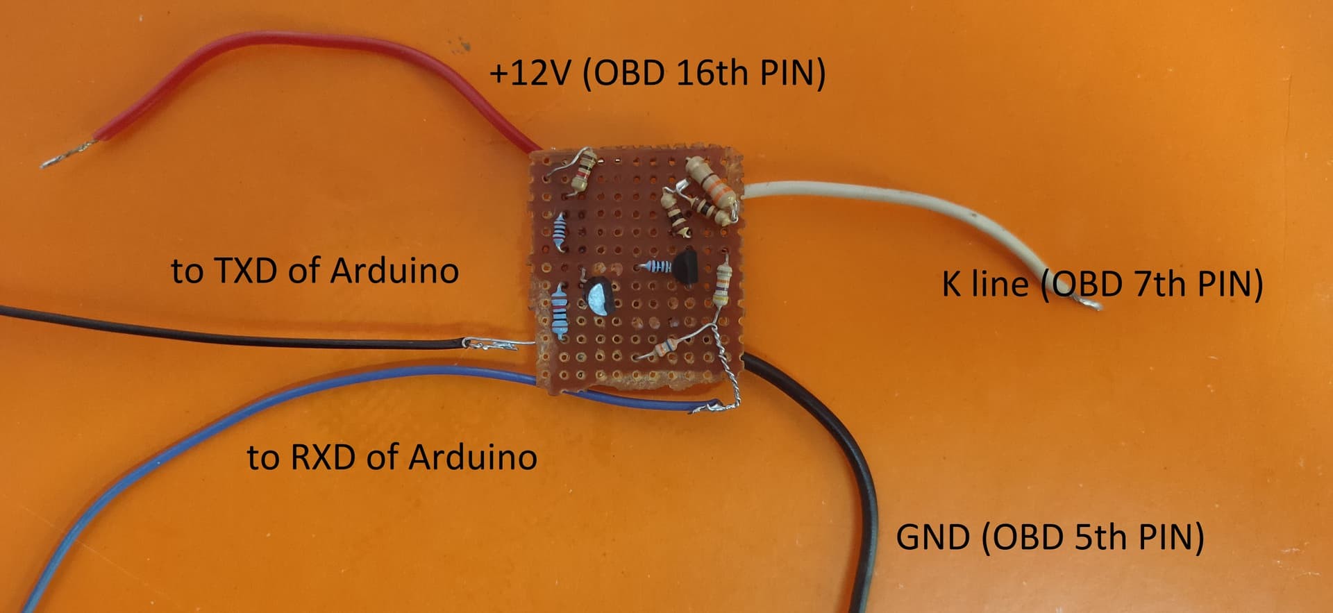
A common K-Line interface circuit for Arduino utilizes NPN transistors (like BC547) and resistors to achieve level shifting and signal inversion necessary for proper communication. The circuit typically performs two key functions:
- Voltage Level Shifting: It converts the 5V transmit signal from the Arduino to a 12V signal suitable for the K-Line and conversely, reduces the 12V K-Line signal to a 5V level that the Arduino can safely read.
- Signal Inversion: The K-Line protocol often requires signal inversion, which the transistor circuit can also handle.
Let’s examine a typical schematic of such a circuit:
In this circuit:
- Transistors (Q1, Q2 – BC547): Act as switches to control the signal flow and perform level shifting.
- Resistors (R1-R5): Set bias voltages, limit current, and ensure proper signal levels. Specific resistor values are crucial for the circuit to function correctly.
Troubleshooting Steps for OBD2 K-Line Communication Failure
When faced with an “init_success = 0” error, systematically troubleshooting the following areas can pinpoint the root cause:
-
Circuit Verification:
- Wiring Errors: Double-check every connection against the schematic. Even a single misplaced wire can disrupt the circuit’s operation. Pay close attention to the transistor pinouts (Emitter, Base, Collector) and ensure they are correctly connected.
- Component Values: Verify that all resistor values (R1, R2, R3, R4, R5) match the schematic and are of the correct tolerance. Incorrect resistor values can lead to improper voltage levels and signal distortion.
- Transistor Type: Confirm that you are using the correct transistor type (BC547 or equivalent NPN transistor). Using the wrong type might result in the circuit not functioning as intended.
- Soldering Quality: Inspect your solder joints. Cold solder joints or bridges can cause intermittent connections or signal loss. Reflow solder joints that appear suspect.
- Power Supply: Ensure the Arduino and the interface circuit are properly powered. Check the voltage levels at different points in the circuit using a multimeter to confirm power is reaching all components.
-
Code Examination:
- Library Compatibility: Verify that the
OBD9141.hlibrary is correctly installed and compatible with your Arduino version and the K-Line protocol your vehicle uses (ISO 9141-2, ISO 14230-4, etc.). - Serial Port Configuration: Double-check that the
AltSoftSerialorSerialport (depending on your code and wiring) is correctly initialized with the appropriate baud rate (typically 9600 for K-Line). - Pin Definitions: Ensure that the RX_PIN and TX_PIN definitions in your code (
#define RX_PIN 8,#define TX_PIN 9) match the Arduino pins you have physically connected to the interface circuit. - Initialization Sequence: Review the
obd.init()function call in your code. Some libraries might require specific initialization parameters or delays. Consult the library documentation for details.
- Library Compatibility: Verify that the
-
K-Line Specific Issues:
- K-Line Pin Connection: Confirm that you have connected the interface circuit’s K-Line output to the correct pin on your vehicle’s OBD2 port. Pin 7 is typically the K-Line pin for ISO 9141-2 and ISO 14230-4 (KWP2000) protocols. Refer to your vehicle’s service manual or OBD2 pinout diagrams for confirmation.
- ECU Compatibility: While K-Line is a standard, some vehicles might have variations or specific implementation details. It’s possible that the standard
OBD9141library might not be fully compatible with your specific ECU. Research your vehicle’s OBD2 protocol and consider trying alternative libraries or approaches if compatibility is suspected. - Termination Resistor: In some K-Line systems, a termination resistor might be required at the ECU end of the K-Line. While often internally present in the ECU, in rare cases, an external termination resistor might be needed. Consult vehicle-specific documentation if termination is suspected as an issue.
- Ground Loops: Ground loops can sometimes interfere with serial communication. Ensure a clean and common ground connection between the Arduino, the interface circuit, and the vehicle’s ground.
-
Debugging Techniques:
- Serial Monitor Output: Utilize
Serial.println()statements in your code to provide more detailed debugging information. For example, print the return values of library functions or intermediate steps in the initialization process. - Multimeter Testing: Use a multimeter to measure voltage levels at various points in the interface circuit and the OBD2 port. This can help identify broken connections, incorrect voltage levels, or short circuits.
- Logic Analyzer/Oscilloscope (Advanced): For in-depth signal analysis, a logic analyzer or oscilloscope can be invaluable. These tools allow you to visualize the actual signals on the K-Line and verify signal timing, voltage levels, and signal integrity.
- Serial Monitor Output: Utilize
Best Practices for Reliable OBD2 K-Line Communication with Arduino
To increase your chances of success and minimize troubleshooting headaches, follow these best practices:
- Use a Proven Schematic: Start with a well-documented and tested K-Line interface circuit schematic. This reduces the chances of design flaws.
- High-Quality Components: Use reputable electronic components with accurate specifications.
- Careful Construction: Build your circuit with meticulous attention to detail, ensuring clean soldering, correct wiring, and secure connections.
- Library Documentation: Thoroughly read the documentation for the OBD2 library you are using. Understand its initialization procedures, function calls, and any specific requirements.
- Vehicle-Specific Information: Research your vehicle’s OBD2 protocol and pinouts. Vehicle-specific information can be crucial for troubleshooting compatibility issues.
- Start Simple: Begin with a minimal setup. Focus on establishing basic communication before attempting to read complex PIDs or implement advanced features.
- Iterative Testing: Test your circuit and code incrementally. After each modification or change, test again to isolate the impact of each step.
Conclusion
Troubleshooting OBD2 K-Line communication with Arduino can be challenging but is ultimately rewarding. By systematically checking your circuit, code, and understanding the nuances of the K-Line protocol, you can overcome communication barriers and successfully interface your Arduino with your car’s diagnostic system. Remember to be patient, methodical, and leverage debugging tools to pinpoint the source of the problem. With careful attention to detail and a structured approach, you’ll be reading live data from your car in no time, unlocking a world of automotive insights.