Want to understand the Obd2 Power Pin and its role in your car’s diagnostics?
This in-depth guide explains the OBD2 connector, focusing on the crucial power pin (pin 16), and how it relates to powering scan tools and ensuring proper communication. We’ll also cover essential aspects like OBD2 protocols, connector types, and troubleshooting tips.
This article provides a comprehensive look at the OBD2 power pin and the broader OBD2 system, going beyond a simple introduction to give you a robust understanding.
You can also refer to the original article for a broader OBD2 overview, or continue reading for a deep dive into the power pin.
Delving Deeper into the OBD2 Connector and Power Pin
The On-Board Diagnostics II (OBD2) system is a standardized system in modern vehicles that allows access to vehicle health information. At the heart of this system is the 16-pin OBD2 connector, a gateway to your car’s computer. When you see the check engine light, a mechanic uses an OBD2 scanner and connects it to this port, usually located under the dashboard near the steering wheel. This connection allows them to read Diagnostic Trouble Codes (DTCs) and access real-time vehicle data.
But what powers this communication? That’s where the OBD2 power pin, specifically pin 16, comes into play.
Understanding the OBD2 System: The malfunction indicator light signals issues, diagnosed via the OBD2 port.
Does Your Car Rely on the OBD2 Power Pin?
Almost all non-electric vehicles manufactured after the mid-1990s are OBD2 compliant. While older cars might have a 16-pin connector, it doesn’t guarantee OBD2 support. Compliance is generally determined by the vehicle’s market and manufacturing date. Regulations mandated OBD2 implementation in phases across different regions and vehicle types.
OBD2 Compliance Guide: Check your vehicle’s origin and manufacturing year to determine OBD2 support.
OBD2 Evolution and the Power Pin’s Consistent Role
The OBD2 standard was born from emissions control regulations in California, starting in the early 1990s. Standardization efforts by the Society of Automotive Engineers (SAE) led to the SAE J1962 standard, which defined the connector and standardized DTCs, ensuring consistency across manufacturers. Throughout the OBD2 rollout, the OBD2 power pin (pin 16) has consistently been part of the standard, providing a reliable power source for diagnostic tools.
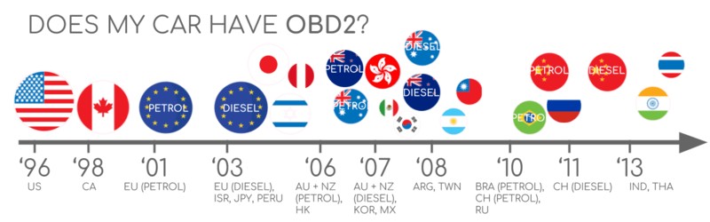
- 1996: OBD2 mandated in the USA for cars and light trucks.
- 2001: Required in the EU for gasoline cars.
- 2003: EU mandate extended to diesel cars (EOBD).
- 2005: OBD2 required in US medium-duty vehicles.
- 2008: US cars must use ISO 15765-4 (CAN) as the OBD2 communication basis.
- 2010: OBD2 required for US heavy-duty vehicles.
OBD2 History: From emissions control origins to widespread adoption across vehicle types.
OBD2 Timeline: A visual overview of the standard’s progressive implementation across years.
OBD2 Future: Exploring OBD3 concepts with remote diagnostics and cloud integration.
The Future of OBD2 and the Power Pin
While OBD2 is evolving, its fundamental principles, including the OBD2 power pin, are likely to remain relevant. Electric vehicles (EVs), however, present a shift. Currently, most EVs don’t fully support standard OBD2 for emissions-related data, as originally intended. They often use manufacturer-specific protocols like UDS. This makes accessing EV data challenging without specialized knowledge and tools, as seen in reverse-engineering efforts for brands like Tesla, Hyundai/Kia, Nissan, and VW/Skoda.
Emerging standards like WWH-OBD and OBDonUDS aim to modernize OBD communication by using the UDS protocol as a foundation, potentially enhancing data richness and streamlining diagnostics.
The concept of OBD3 envisions telematics integration, potentially adding radio transponders to vehicles for automated emission checks. This raises data privacy concerns but offers convenience. Current technologies like the CANedge2 WiFi CAN logger and CANedge3 3G/4G CAN logger already facilitate wireless OBD2 data transmission.
There’s also debate about third-party access to OBD2 data. Some manufacturers propose limiting OBD2 access while driving, centralizing data collection instead. This could impact the aftermarket OBD2 service industry but is driven by security concerns and OEM data control ambitions. Despite these potential shifts, the physical OBD2 port and its power pin remain crucial for initial connection and potentially for accessing limited diagnostic data even in future systems.
OBD2 in EVs: Electric vehicles often deviate from standard OBD2, posing data access challenges.
Deep Dive into the CAN Bus Guide
Want to become a CAN bus expert and understand the underlying communication of OBD2?
Our comprehensive 160+ page PDF guide offers 12 detailed introductions to CAN bus and related technologies.
Download now
OBD2 Standards and the Connector’s Power Supply
OBD2 functions as a high-level communication protocol built upon lower-level communication methods like CAN bus. Similar to protocols like J1939, CANopen, and NMEA 2000, OBD2 relies on standardized connectors, protocols, and parameter IDs (PIDs). These standards are structured around the 7-layer OSI model, with both SAE and ISO standards contributing to different layers, reflecting US (SAE) and EU (ISO) specifications. The OBD2 power pin is consistently defined across these standards as pin 16, ensuring that diagnostic tools can reliably draw power.
OBD2 and CAN Bus in the OSI Model: Illustrating the layered communication architecture and relevant standards.
OBD2 Connector Pinout: Diagram of a Type A OBD2 connector, highlighting pin assignments.
The OBD2 Connector [SAE J1962] and Pin 16
The 16-pin OBD2 connector, detailed in SAE J1962 / ISO 15031-3, is your primary interface for vehicle diagnostics. Pin 16 is specifically designated as the battery power supply pin. This pin typically provides battery voltage even when the ignition is off, allowing scan tools to operate.
Key aspects of the OBD2 connector and power pin 16:
- Location: Usually near the steering wheel, but sometimes hidden.
- Pin 16: Battery Power: Supplies power (often 12V or 24V) directly from the car battery. This is the obd2 power pin.
- Pinout Variation: Pin assignments vary based on the communication protocol.
- CAN bus: Common lower-layer protocol using pins 6 (CAN-H) and 14 (CAN-L).
OBD2 Connector Types: A vs. B and Power Pin Voltage
You may encounter Type A and Type B OBD2 connectors. Type A is standard in cars, while Type B is common in medium and heavy-duty vehicles. While pinouts are similar, a key difference is the power supply voltage provided by pin 16. Type A typically provides 12V, while Type B provides 24V. Baud rates can also differ, with cars often using 500K and heavy-duty vehicles frequently using 250K (more recently with 500K support).
Type B connectors have a distinguishing interrupted groove. A Type B OBD2 adapter cable is compatible with both Type A and B sockets, but a Type A adapter will not fit into a Type B socket. Always verify the voltage requirements of your scan tool and the voltage supplied by pin 16 of your vehicle’s OBD2 port to avoid damage.
OBD2 Connector Types A and B: Illustrating the physical differences and voltage variations (12V vs 24V) at pin 16.
OBD2 vs CAN bus: Highlighting the relationship and ISO 15765 standards.
OBD2 and CAN bus [ISO 15765-4]: Communication and Power
Since 2008, CAN bus (ISO 15765) has been mandatory for OBD2 communication in US vehicles. ISO 15765-4 (Diagnostics over CAN or DoCAN) standardizes the CAN interface for diagnostic equipment, specifying parameters for the physical, data link, and network layers. Crucially, the OBD2 power pin ensures consistent power delivery for CAN communication and diagnostic processes.
ISO 15765-4 specifications include:
- Bit-rate: 250K or 500K.
- CAN IDs: 11-bit or 29-bit.
- CAN IDs for OBD requests/responses.
- Diagnostic CAN frame data length: 8 bytes.
- OBD2 adapter cable length: Maximum 5 meters.
OBD2 CAN Identifiers (11-bit, 29-bit) and Power for Communication
OBD2 communication relies on request/response message exchanges. Most cars use 11-bit CAN IDs for OBD2. Functional addressing (ID 0x7DF) queries all OBD2-compatible ECUs. Physical addressing (IDs 0x7E0-0x7E7) targets specific ECUs. ECU responses typically use 11-bit IDs 0x7E8-0x7EF, with 0x7E8 (ECM) being the most common.
Some vehicles, particularly vans and heavy-duty vehicles, use 29-bit CAN identifiers for OBD2. Functional addressing ID is 0x18DB33F1, and responses use IDs 0x18DAF100 to 0x18DAF1FF.
The consistent power provided by the OBD2 power pin is essential for reliable CAN communication in both 11-bit and 29-bit ID scenarios.
OBD2 Request/Response: Illustrating the communication flow and PID data parameters.
OBD2 vs Proprietary CAN: Comparing standardized OBD2 communication with OEM-specific CAN protocols.
OBD2 vs. Proprietary CAN Protocols and Power Considerations
Vehicle ECUs primarily use OEM-specific CAN protocols for internal functions, not OBD2. OBD2 is an additional protocol layer for diagnostics. OEM protocols vary by brand, model, and year, and are generally proprietary. Connecting a CAN bus data logger to the OBD2 port may reveal OEM-specific CAN data, but access can be blocked by a gateway in newer vehicles, limiting communication to OBD2.
OBD2 operates in parallel to OEM protocols. The OBD2 power pin primarily facilitates the diagnostic protocol, not the OEM-specific CAN communication.
Bit-rate and ID Validation & Power Supply Stability
OBD2 can use two bit-rates (250K, 500K) and two CAN ID lengths (11-bit, 29-bit), resulting in four combinations. 500K and 11-bit IDs are common in modern cars. ISO 15765-4 outlines initialization sequences to determine the correct combination, relying on mandatory OBD2 responses and CAN error frame detection. Stable power from the OBD2 power pin is crucial for accurate bit-rate and ID validation during initialization.
Newer ISO 15765-4 versions address OBDonUDS (OBD on Unified Diagnostic Service) alongside OBDonEDS (OBD on emission diagnostic service). OBDonEDS is prevalent in non-EV cars, while WWH-OBD/OBDonUDS is common in EU trucks/buses. Protocol detection involves sending UDS requests to identify OBDonUDS support.
OBD2 Bit-rate and CAN ID Validation Flowchart: Illustrating the process for determining communication parameters.
OBD2 Lower-Layer Protocols: Overview of the five main lower-layer protocols, including CAN (ISO 15765).
Five Lower-Layer OBD2 Protocols and Connector Pinouts
While CAN (ISO 15765) dominates modern OBD2, older cars might use other lower-layer protocols. Understanding these protocols and their pinouts is useful for diagnosing older vehicles. The OBD2 power pin (pin 16) remains consistent across these protocols, but other pin assignments may vary.
- ISO 15765 (CAN bus): Dominant since 2008.
- ISO14230-4 (KWP2000): Common in 2003+ Asian cars.
- ISO 9141-2: Used in EU, Chrysler & Asian cars (2000-04).
- SAE J1850 (VPW): Older GM cars.
- SAE J1850 (PWM): Older Ford cars.
Transporting OBD2 Messages via ISO-TP [ISO 15765-2] and Power Reliability
OBD2 data is transmitted over CAN bus using ISO-TP (ISO 15765-2), a transport protocol enabling payloads exceeding 8 bytes. This is essential for data like VIN or DTCs. ISO 15765-2 handles segmentation, flow control, and reassembly. For smaller OBD2 data packets, ISO 15765-2 uses ‘Single Frame’ (SF) format, with the first byte indicating payload length, leaving 7 bytes for OBD2 data. Consistent power from the OBD2 power pin ensures reliable ISO-TP communication, especially for multi-frame messages.
ISO-TP Frame Types: Illustrating Single Frame, First Frame, Consecutive Frame, and Flow Control frame types in ISO 15765-2.
The OBD2 Diagnostic Message [SAE J1979, ISO 15031-5] and Power for Data Access
An OBD2 message consists of an identifier, data length (PCI field), and data (Mode, PID, data bytes). Understanding this structure is crucial for interpreting OBD2 communication. Reliable power from pin 16 is fundamental to consistent message transmission and reception.
OBD2 Message Structure: Breakdown of an OBD2 message frame, including Mode, PID, and data bytes.
Example: OBD2 Request/Response and Power for Scan Tools
Consider a request for ‘Vehicle Speed’. A scan tool sends a request (CAN ID 0x7DF, Mode 0x01, PID 0x0D). The car responds (CAN ID 0x7E8) with speed data. Decoding PID 0x0D reveals the speed in km/h. The OBD2 power pin is essential for powering the external scan tool to initiate and receive these request/response cycles.
OBD2 Request/Response Example: Illustrating a vehicle speed request and response sequence.
OBD2 PID Example: Vehicle Speed (PID 0D) data decoding illustration.
OBD2 Service Modes: Overview of the 10 standardized OBD2 service modes (diagnostic services).
The 10 OBD2 Services (Modes) and Power for Diagnostics
OBD2 defines 10 diagnostic services (modes). Mode 0x01 provides real-time data, while others handle DTCs and freeze frame data. Vehicles aren’t required to support all modes, and OEM-specific modes may exist. Modes are indicated in the second byte of OBD2 messages. In responses, 0x40 is added to the mode value. The availability of power through the OBD2 power pin enables scan tools to access these various diagnostic modes.
OBD2 Parameter IDs (PIDs) and Power for Data Parameters
Each OBD2 mode uses Parameter IDs (PIDs). Mode 0x01, for example, includes ~200 standardized PIDs for real-time data like speed and RPM. However, vehicles typically support only a subset of PIDs. PID 0x00 in mode 0x01 is crucial: if an ECU supports OBD2, it must support mode 0x01 PID 0x00. Responding to this PID indicates support for PIDs 0x01-0x20. PIDs 0x20, 0x40, etc., indicate support for subsequent PID ranges. The OBD2 power pin ensures that diagnostic tools have the necessary power to request and process data from these PIDs.
OBD2 Request/Response with PIDs: Reinforcing the structure of request and response frames with PID parameters.
OBD2 PID Overview Tool: Screenshot of a tool for exploring and understanding OBD2 PIDs.
Tip: OBD2 PID Overview Tool and Power for Tool Operation
SAE J1979 and ISO 15031-5 appendices detail scaling information for OBD2 PIDs, enabling data decoding into physical values. Our OBD2 PID overview tool assists in constructing request frames and decoding responses. This tool, like any OBD2 diagnostic tool, relies on power from the OBD2 power pin to function.
OBD2 PID overview tool
Link to OBD2 PID Overview Tool: Direct link to the online tool for PID exploration.
Logging and Decoding OBD2 Data: Powering Data Loggers
Here’s a practical example of logging OBD2 data using a CANedge CAN bus data logger. The CANedge allows custom CAN frame transmission for OBD2 logging and connects via an OBD2-DB9 adapter cable. These data loggers are powered via the OBD2 power pin.
OBD2 Data Logger Setup: Illustrating the connection of an OBD2 data logger for PID request and response capture.
Bit-rate Validation: Testing bit-rate using a CAN tool to ensure successful communication.
Supported PIDs Validation: Reviewing responses to ‘Supported PIDs’ requests in asammdf software.
#1: Test Bit-rate, IDs & Supported PIDs with Power
ISO 15765-4 describes bit-rate and ID determination. Using a CANedge data logger (powered by OBD2 power pin), you can:
- Test 500K bit-rate (or 250K).
- Use the validated bit-rate.
- Send ‘Supported PIDs’ requests.
- Determine 11-bit or 29-bit IDs from responses.
- Identify supported PIDs from response data.
Plug-and-play configurations are available for these tests. Most 2008+ non-EV cars support 40-80 PIDs via 500K bit-rate, 11-bit CAN IDs, and OB