Understanding your vehicle’s health is becoming increasingly accessible, and the key lies in the Obd2 Scanner Connector. This port, standardized across most modern vehicles, is your gateway to a wealth of diagnostic information. Whether you’re a seasoned mechanic or a car owner keen on preventative maintenance, grasping the nuances of the OBD2 scanner connector is crucial. This guide will delve into everything you need to know, from its location and pinout to its role in modern automotive diagnostics, ensuring you’re equipped to leverage this powerful tool effectively.
Unveiling OBD2: On-Board Diagnostics II
OBD2, short for On-Board Diagnostics II, is essentially your car’s internal health monitoring system. It’s a standardized protocol implemented in vehicles to provide access to diagnostic trouble codes (DTCs) and real-time data. Think of it as a universal translator, allowing diagnostic tools, particularly OBD2 scanners, to communicate with your car’s computer.
You’ve likely encountered OBD2 in action without even realizing it. That “check engine light” illuminating on your dashboard? That’s OBD2 signaling a potential issue. When you take your car to a mechanic, their first step is often plugging an OBD2 scanner into the OBD2 scanner connector. This simple connection allows them to quickly identify problems, read sensor data, and ultimately, get you back on the road faster.
Understanding OBD2: The malfunction indicator light (MIL) is a common sign that your vehicle’s on-board diagnostic system has detected an issue, often requiring the use of an OBD2 scanner.
Does Your Car Have an OBD2 Scanner Connector?
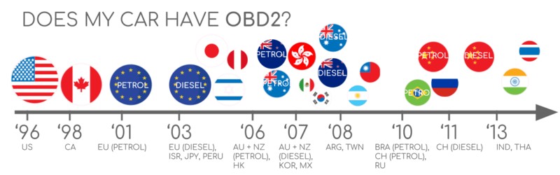
The good news is, if you own a car manufactured in recent decades, the answer is almost certainly yes! OBD2 became mandatory in the USA for cars and light trucks in 1996, with the European Union following suit in 2001 for gasoline cars and 2003 for diesel vehicles. While older cars might have a 16-pin connector that resembles an OBD2 scanner connector, it doesn’t guarantee OBD2 compliance.
To quickly check for OBD2 compliance, consider these guidelines based on where and when your car was initially purchased:
A Brief History of OBD2 and the OBD2 Scanner Connector
The story of OBD2 begins in California, driven by the California Air Resources Board (CARB). In 1991, CARB mandated OBD systems in new cars to monitor and control emissions. The Society of Automotive Engineers (SAE) played a pivotal role in standardizing the system, leading to the OBD2 scanner connector and standardized Diagnostic Trouble Codes (DTCs) across different manufacturers through SAE J1962.
The rollout of OBD2 was a phased process:
- 1996: OBD2 becomes mandatory in the USA for cars and light trucks.
- 2001: OBD2 required in the EU for gasoline vehicles.
- 2003: EU mandates OBD2 for diesel vehicles (EOBD).
- 2005: OBD2 becomes required in the US for medium-duty vehicles.
- 2008: US regulations mandate ISO 15765-4 (CAN) as the foundation for OBD2.
- 2010: OBD2 becomes mandatory in the US for heavy-duty vehicles.
The Future of OBD2 and Diagnostic Connectors
While OBD2 remains the standard for vehicle diagnostics, the automotive landscape is evolving. Electric vehicles (EVs), for example, are not obligated to support OBD2 in the traditional sense. Many EVs utilize OEM-specific UDS communication, making standard OBD2 scanners less effective. However, dedicated efforts in reverse engineering are making data access from EVs increasingly possible.
Emerging protocols like WWH-OBD (World Wide Harmonized OBD) and OBDonUDS (OBD on UDS) are being developed to address the limitations of traditional OBD2. These protocols aim to enhance OBD communication by leveraging the UDS protocol, offering richer data and more streamlined diagnostics.
The concept of OBD3 introduces telematics to vehicle diagnostics. Imagine cars equipped with radio transponders that automatically transmit VIN and DTCs to a central server. This could revolutionize emission control checks and vehicle monitoring, though it also raises privacy concerns.
Furthermore, there’s a debate about third-party access to OBD2 data. While initially intended for repair shops, OBD2 is now widely used by third-party services for real-time data access. However, some manufacturers are exploring ways to restrict this access, potentially shifting control of automotive data back to OEMs.
The evolving landscape of OBD2: Electric vehicles and discussions around data access are shaping the future of automotive diagnostics and the role of the OBD2 scanner connector.
Deep Dive into OBD2 Standards and the Connector
OBD2 operates as a higher-layer protocol, much like a language spoken over a communication channel. In this context, CAN (Controller Area Network) bus acts as the communication method, similar to a phone line. This places OBD2 in the same family as other CAN-based protocols like J1939, CANopen, and NMEA 2000.
OBD2 standards meticulously define various aspects, most importantly the OBD2 scanner connector, lower-layer communication protocols, and OBD2 Parameter IDs (PIDs). These standards can be visualized using the 7-layer OSI model, with both SAE (US standards) and ISO (EU standards) contributing to different layers. Notably, SAE J1979 aligns with ISO 15031-5, and SAE J1962 closely mirrors ISO 15031-3.
The OBD2 Scanner Connector: SAE J1962 Standard
The OBD2 scanner connector, formally defined by SAE J1962 / ISO 15031-3, is the physical interface that allows you to tap into your car’s diagnostic data. This 16-pin connector, also known as the Data Link Connector (DLC), is designed for easy access.
Key features of the OBD2 scanner connector:
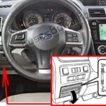
- Location: Typically found near the steering wheel, but its exact placement can vary and might be concealed.
- Pin 16: Provides battery power, often active even when the ignition is off.
- Pinout Variations: The specific pinout configuration depends on the communication protocol used by the vehicle.
- CAN Bus Integration: In most modern cars, CAN bus is the primary lower-layer protocol, utilizing pins 6 (CAN-H) and 14 (CAN-L).
OBD2 Connector Types: Type A vs. Type B
You might encounter two main types of OBD2 scanner connectors: Type A and Type B. Type A is standard in cars and light vehicles, while Type B is more common in medium and heavy-duty vehicles.
While both types share similar pinouts, the key differences lie in power supply output (12V for Type A, 24V for Type B) and often the baud rate. Cars typically use 500K baud rate, whereas heavy-duty vehicles often use 250K (with increasing support for 500K).
Visually, Type B connectors have a distinguishing interrupted groove in the middle. This means a Type B OBD2 adapter cable is generally compatible with both Type A and Type B sockets, but a Type A adapter will not fit into a Type B socket.
OBD2 and CAN Bus Communication via the Connector
Since 2008, CAN bus has become the mandatory lower-layer protocol for OBD2 in US vehicles, as per ISO 15765. ISO 15765-4, also known as Diagnostics over CAN (DoCAN), outlines specific restrictions and standards for CAN implementation in OBD2 systems, focusing on the physical, data link, and network layers.
Key aspects of OBD2 over CAN (ISO 15765-4):
- Bit Rate: Must be either 250K or 500K.
- CAN IDs: Supports both 11-bit and 29-bit CAN identifiers.
- Standardized CAN IDs: Specific CAN IDs are designated for OBD requests and responses.
- Data Frame Length: Diagnostic CAN frames must have a data length of 8 bytes.
- Cable Length Limit: OBD2 adapter cables should not exceed 5 meters.
CAN Identifiers for OBD2 Communication
OBD2 communication relies on a request-response message structure. In most cars using 11-bit CAN IDs, the ‘Functional Addressing’ ID 0x7DF is used to query all OBD2-compatible ECUs. ‘Physical Addressing’ IDs (0x7E0-0x7E7) can target specific ECUs, but are less frequently used.
ECUs respond with 11-bit IDs in the range of 0x7E8-0x7EF. The most common response ID is 0x7E8 (Engine Control Module – ECM), followed by 0x7E9 (Transmission Control Module – TCM).
Some vehicles, particularly vans and medium/heavy-duty vehicles, may use extended 29-bit CAN identifiers for OBD2 communication. In this case, the ‘Functional Addressing’ CAN ID is 0x18DB33F1. Responses are typically in the CAN ID range of 0x18DAF100 to 0x18DAF1FF, often seen as J1939 PGN 0xDA00 (55808).
OBD2 vs. OEM-Specific CAN Protocols
It’s important to understand that OBD2 is an additional protocol layer on top of the vehicle’s core communication network. Vehicle ECUs primarily function using proprietary CAN protocols defined by the Original Equipment Manufacturer (OEM). These OEM-specific protocols are unique to brand, model, and year, and are usually not publicly documented (requiring reverse engineering to decipher).
Connecting a CAN bus data logger to the OBD2 scanner connector might reveal OEM-specific CAN data, often broadcast at high rates. However, newer vehicles frequently employ a ‘gateway’ that restricts access to this raw CAN data, allowing only OBD2 communication through the connector.
Understanding the layers: OBD2 is a standardized diagnostic protocol that operates alongside, but separately from, the proprietary CAN protocols used for core vehicle functions.
Bit-rate and ID Validation for OBD2 Scanner Connection
OBD2 over CAN can utilize two bit rates (250K, 500K) and two CAN ID lengths (11-bit, 29-bit), resulting in four possible combinations. Modern cars commonly use 500K and 11-bit IDs. Diagnostic tools should systematically validate these parameters to ensure correct communication.
ISO 15765-4 provides guidelines for an initialization sequence to determine the correct combination. This process relies on the mandatory support for OBD2 mode 0x01 PID 0x00 in compliant vehicles and detects CAN error frames caused by incorrect bit-rate settings.
More recent versions of ISO 15765-4 also consider OBDonUDS, in addition to OBDonEDS (OBD on Emission Diagnostic Service). While OBDonEDS (commonly referred to as OBD2, SAE OBD, EOBD, or ISO OBD) is prevalent in most non-EV cars today, WWH-OBD is primarily used in EU trucks and buses.
Tools may also test for OBDonUDS support by sending UDS requests with specific IDs and service codes. Vehicles supporting OBDonUDS should respond to these requests.
Legacy OBD2 Protocols
While CAN bus (ISO 15765) dominates modern OBD2 systems, older vehicles (pre-2008) might utilize one of five lower-layer protocols. Understanding these legacy protocols can be helpful when working with older cars. The OBD2 scanner connector pinout can sometimes indicate the protocol in use.
- ISO 15765 (CAN bus): Standard in US cars since 2008, and widely used today.
- ISO14230-4 (KWP2000): Common in 2003+ cars, particularly in Asia.
- ISO 9141-2: Used in EU, Chrysler, and Asian cars (2000-2004).
- SAE J1850 (VPW): Primarily used in older GM vehicles.
- SAE J1850 (PWM): Primarily used in older Ford vehicles.
ISO-TP: Transporting OBD2 Messages via the OBD2 Scanner Connector
All OBD2 communication over CAN bus uses ISO-TP (ISO 15765-2), a transport protocol that allows for data payloads exceeding the 8-byte limit of CAN frames. This is essential for transmitting larger OBD2 messages like VIN requests or DTC lists. ISO-TP handles segmentation, flow control, and reassembly of these larger messages.
In cases where OBD2 data fits within a single CAN frame, ISO-TP utilizes ‘Single Frame’ (SF) formatting. The first byte of the data payload (PCI field) indicates the payload length, leaving 7 bytes for OBD2-related data.
Decoding the OBD2 Diagnostic Message from the Connector
To understand OBD2 communication at a granular level, let’s examine a raw ‘Single Frame’ OBD2 CAN message. Simplified, an OBD2 message consists of an identifier, data length (PCI field), and data. The data portion is further broken down into Mode, Parameter ID (PID), and data bytes.
Example: OBD2 Request and Response via the Connector
Consider a request for ‘Vehicle Speed’. An external tool sends a request message via the OBD2 scanner connector with CAN ID 0x7DF and two payload bytes: Mode 0x01 and PID 0x0D. The vehicle responds with CAN ID 0x7E8 and three payload bytes, including the speed value in the fourth byte (0x32, which is 50 in decimal).
By consulting OBD2 PID documentation, we can determine that PID 0x0D represents Vehicle Speed, and the value 50 corresponds to 50 km/h.
OBD2 Services (Modes) Accessed Through the Connector
OBD2 defines 10 diagnostic services, often referred to as modes. Mode 0x01 provides real-time data, while others are used for accessing and clearing DTCs or retrieving freeze frame data.
Vehicles are not required to support all 10 OBD2 modes, and manufacturers may implement additional OEM-specific modes beyond the standard set.
In OBD2 messages, the mode is indicated in the second byte. In a request, the mode value is used directly (e.g., 0x01). In a response, 0x40 is added to the requested mode value (e.g., 0x41 for a response to mode 0x01).
OBD2 Parameter IDs (PIDs) and the Scanner Connector
Within each OBD2 mode, Parameter IDs (PIDs) are used to specify the data being requested. For example, mode 0x01 contains approximately 200 standardized PIDs for real-time data like speed, RPM, and fuel level. However, vehicles typically support only a subset of these PIDs.
One PID is particularly important: PID 0x00 in mode 0x01. If an emissions-related ECU supports OBD2 services at all, it must support mode 0x01 PID 0x00. Responding to this PID, the ECU indicates its support for PIDs 0x01-0x20. This makes PID 0x00 a fundamental compatibility test for OBD2. Similarly, PIDs 0x20, 0x40, and so on, can be used to determine support for subsequent PID ranges within mode 0x01.
OBD2 PID Overview Tools
SAE J1979 and ISO 15031-5 appendices provide scaling information for standard OBD2 PIDs, enabling the conversion of raw data into physical values. Online tools, like the OBD2 PID overview tool mentioned in the original article, simplify the process of constructing OBD2 requests and decoding responses.
OBD2 PID overview tool
Practical Guide: Logging and Decoding OBD2 Data via the Connector
Let’s walk through a practical example of logging OBD2 data using a CANedge CAN bus data logger connected via the OBD2 scanner connector.
The CANedge, and similar devices, allows you to configure custom CAN frames for transmission, making it suitable for sending OBD2 requests. Connecting the CANedge to your vehicle’s OBD2 scanner connector is straightforward using an OBD2-DB9 adapter cable.
Testing the connection: Verifying successful CAN frame transmission at different bit rates is crucial for establishing reliable OBD2 communication.
Analyzing responses: Reviewing responses to ‘Supported PIDs’ requests using software like asammdf helps determine vehicle-specific OBD2 capabilities.
Step 1: Bit-rate, ID, and Supported PID Validation
Follow these steps (as outlined in ISO 15765-4) to determine the correct communication parameters for your vehicle:
- Test CAN frame transmission at 500K baud rate. If successful, proceed; otherwise, try 250K.
- Use the validated bit rate for subsequent communication.
- Send multiple ‘Supported PIDs’ requests and analyze the responses.
- Determine 11-bit or 29-bit CAN ID usage based on response IDs.
- Identify supported PIDs from the response data.
Pre-configured settings are often available for these tests. Most post-2008 non-EV cars typically support 40-80 PIDs, using 500K bit rate, 11-bit CAN IDs, and the OBD2/OBDonEDS protocol.
Analyzing responses to ‘Supported PIDs’ requests, as shown in the asammdf GUI example, often reveals multiple responses due to the use of the 0x7DF request ID, which broadcasts to all ECUs. Since all OBD2/OBDonEDS-compliant ECUs must support service 0x01 PID 0x00, numerous responses to this PID are common. For subsequent requests, focusing on the ECM ECU (0x7E8) using ‘Physical Addressing’ (CAN ID 0x7E0) can reduce bus load.
Step 2: Configuring OBD2 PID Requests for Data Logging
Once you’ve identified supported PIDs and communication parameters, configure your data logger to request the PIDs you’re interested in. Consider these points:
- CAN IDs: Switch to ‘Physical Addressing’ request IDs (e.g., 0x7E0) to minimize multiple responses.
- Request Spacing: Introduce a delay of 300-500 ms between OBD2 requests to prevent overwhelming ECUs.
- Power Management: Implement triggers to stop transmissions when the vehicle is inactive to avoid battery drain.
- Data Filtering: Apply filters to record only OBD2 responses if OEM-specific CAN data is also present.
With these configurations, your device is ready to log raw OBD2 data directly from the OBD2 scanner connector.
Example configuration: A transmit list for a CANedge data logger, demonstrating how to set up OBD2 PID requests for efficient data acquisition.
Data visualization: asammdf software allows for DBC decoding and visual plotting of OBD2 data, transforming raw signals into meaningful insights.
Step 3: DBC Decoding of Raw OBD2 Data
To make sense of the logged raw OBD2 data, you need to decode it into physical values. Decoding information is available in ISO 15031-5/SAE J1979 and online resources like Wikipedia. A free OBD2 DBC file, like the one provided by CS Electronics, simplifies DBC decoding in most CAN bus software tools.
Decoding OBD2 data is more complex than standard CAN signal decoding. Because different OBD2 PIDs share the same CAN ID (e.g., 0x7E8), the CAN ID alone isn’t enough to identify the signal. You need to consider the CAN ID, OBD2 mode, and OBD2 PID to correctly interpret the data. This multiplexing technique, known as ‘extended multiplexing,’ can be effectively managed using DBC files.
CANedge: Your OBD2 Data Logging Solution
The CANedge offers a user-friendly solution for recording OBD2 data. Simply connect it to the OBD2 scanner connector of your car or truck, and it will log data to an SD card (8-32GB). Free software and APIs, along with the OBD2 DBC file, are available for easy data decoding and analysis.
OBD2 logger intro CANedge
Multi-Frame OBD2 Examples via the Connector
Most examples so far have focused on single-frame OBD2 communication. However, OBD2 also supports multi-frame communication via ISO-TP for larger data payloads. Multi-frame communication involves flow control frames. A common practice is to transmit a static flow control frame approximately 50ms after the initial request.
Software tools like CANedge MF4 decoders are essential for handling multi-frame OBD2 responses.
Example 1: Retrieving Vehicle Identification Number (VIN)
The Vehicle Identification Number (VIN) is crucial for various applications. To retrieve the VIN using OBD2, you use mode 0x09 and PID 0x02.
The process involves sending a Single Frame request with mode 0x09 and PID 0x02. The vehicle responds with a multi-frame response, starting with a First Frame containing length information, mode, PID, and Number Of Data Items (NODI). The subsequent data bytes contain the VIN, which can be converted from HEX to ASCII.
Example 2: Multi-PID Request (6x)
OBD2 allows requesting up to 6 mode 0x01 PIDs in a single request frame. The ECU responds with data for supported PIDs, potentially using multi-frame responses. While efficient, this method complicates data decoding, especially with generic OBD2 DBC files. It’s generally not recommended for practical data logging due to decoding complexity.
Decoding multi-PID responses requires careful consideration of payload structure and PID order, making generic DBC files less effective. Custom scripts and recording request messages alongside responses can aid in decoding, but scaling such approaches can be challenging.
Example 3: Diagnostic Trouble Codes (DTCs) via the OBD2 Scanner Connector
OBD2 mode 0x03, ‘Show stored Diagnostic Trouble Codes,’ retrieves emissions-related DTCs. The request doesn’t include a PID. The ECU responds with the number of stored DTCs and the DTC data (2 bytes per DTC). Multi-frame responses are used when more than two DTCs are present.
DTC values are 2-byte codes, categorized and detailed according to ISO 15031-5/ISO 15031-6. Online OBD2 DTC lookup tools like repairpal.com can be used to decode these codes.
Real-World Applications of OBD2 Data Logging
OBD2 data logging offers numerous practical applications in the automotive world:
Car Data Logging
OBD2 data can be used for fuel efficiency analysis, driving behavior improvement, prototype part testing, and insurance telematics.
obd2 logger
Real-Time Diagnostics
OBD2 interfaces facilitate real-time streaming of vehicle data for immediate issue diagnosis.
obd2 streaming
Predictive Maintenance
IoT-enabled OBD2 loggers enable remote vehicle monitoring for predictive maintenance and breakdown prevention.
predictive maintenance
Vehicle Black Box
OBD2 loggers can act as ‘black boxes’ for accident data recording, dispute resolution, and detailed diagnostics.
can bus blackbox
Have an OBD2 data logging application in mind? Reach out for expert consultation!
Contact us
Explore our guides section for more introductory articles or download our comprehensive Ultimate Guide PDF.
Ready to start logging or streaming OBD2 data?
Get your OBD2 data logger today!
Buy now Contact us
Further Reading
OBD2 DATA LOGGER: EASILY LOG & CONVERT OBD2 DATA
CANEDGE2 – PRO CAN IoT LOGGER
[