Need to understand the connection between OBD2 and CAN bus in modern vehicles?
This guide provides a detailed introduction to the On-Board Diagnostics (OBD2) protocol and its critical relationship with the Controller Area Network (CAN) bus. We’ll explore the OBD2 connector, how OBD2 Parameter IDs (PIDs) are transmitted over CAN, and practical insights into leveraging Obd2 To Can for vehicle diagnostics and data acquisition.
This is your in-depth guide to understanding OBD2 to CAN, designed to be comprehensive and SEO-optimized for an English-speaking audience.
You can also refer to the original article for supplementary information and visuals.
Delving into OBD2: On-Board Diagnostics Explained
OBD2 is essentially your car’s internal health monitoring system. It’s a standardized protocol that enables access to diagnostic trouble codes (DTCs) and real-time vehicle data through a universal OBD2 connector.
You’re likely already familiar with OBD2 in some form. Have you ever seen the check engine light illuminate on your dashboard?
That light is your vehicle signaling a potential issue. When you take your car to a mechanic, they use an OBD2 scanner to pinpoint the problem.
Mechanics connect an OBD2 reader to the 16-pin OBD2 connector, typically located near the steering wheel. This tool sends ‘OBD2 requests’ to the vehicle, and the car responds with ‘OBD2 responses’. These responses can contain valuable information like speed, fuel level, or DTCs, significantly speeding up the diagnostic process.
OBD2 Compatibility: Is Your Car Equipped?
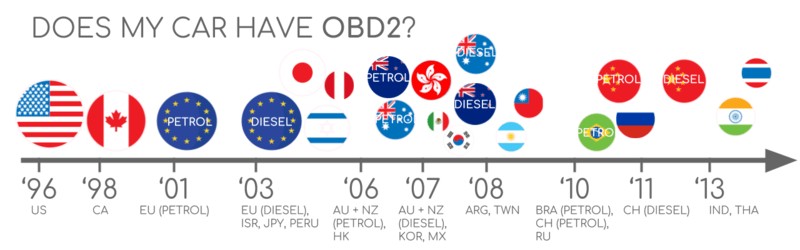
The answer is likely yes, especially if you own a newer, non-electric vehicle. OBD2 is standard in almost all modern cars, and crucially, most of these systems communicate over CAN bus. For older vehicles, even if a 16-pin OBD2 port is present, it might not fully support the OBD2 protocol. A key indicator of OBD2 compliance is the vehicle’s manufacturing date and region of sale:
A Brief History of OBD2
OBD2’s origins trace back to California, where the California Air Resources Board (CARB) mandated OBD in all new vehicles from 1991 onwards for emissions monitoring.
The Society of Automotive Engineers (SAE) further developed the standard, leading to standardized DTCs and the universal OBD connector (SAE J1962).
The OBD2 standard was implemented progressively:
- 1996: OBD2 became mandatory in the USA for cars and light trucks.
- 2001: Required in the EU for gasoline-powered cars.
- 2003: Extended to diesel cars in the EU (EOBD).
- 2005: OBD2 required in the US for medium-duty vehicles.
- 2008: US vehicles mandated to use ISO 15765-4 (CAN) as the foundation for OBD2 communication, solidifying the link between OBD2 to CAN.
- 2010: OBD2 became mandatory for heavy-duty vehicles in the US.
The Future of OBD2
OBD2 is expected to remain relevant, but its form is evolving.
Here are key trends shaping the future of OBD2 and its relationship to CAN:
Initially designed for emissions control, regulatory OBD2 requirements don’t necessarily extend to electric vehicles. Consequently, most modern EVs do not support standard OBD2 requests. Instead, they often utilize OEM-specific UDS communication protocols. This makes accessing data from EVs challenging without reverse-engineered decoding rules. However, resources are emerging for specific EV brands like Tesla, Hyundai/Kia, Nissan, and VW/Skoda, showcasing efforts to bridge the gap between OBD2 to CAN and EV diagnostics.
OBD2’s limitations in data richness and lower-layer protocols have spurred the development of alternatives like WWH-OBD (World Wide Harmonized OBD) and OBDonUDS (OBD on UDS). These advancements aim to enhance OBD communication by using the UDS protocol as a base, representing a shift in how OBD2 to CAN communication might evolve. For a deeper understanding, explore introductions to UDS.
In our increasingly connected world, traditional OBD2 emission checks seem outdated. Manual inspections are time-consuming and costly.
The proposed solution is OBD3 – integrating telematics into all vehicles.
OBD3 envisions adding a small radio transponder to vehicles, enabling wireless transmission of the Vehicle Identification Number (VIN) and DTCs to a central server for automated checks.
Current technologies already facilitate CAN or OBD2 data transfer via WiFi/cellular networks, exemplified by devices like the CANedge2 WiFi CAN logger and CANedge3 3G/4G CAN logger.
While offering convenience and cost savings, OBD3 raises privacy concerns related to surveillance.
Originally intended for stationary emission controls, OBD2 is now widely used by third parties for real-time data generation via OBD2 dongles, CAN loggers, and more. However, the German car industry is seeking to restrict this access:
“OBD has been designed to service cars in repair shops. In no way has it been intended to allow third parties to build a form of data-driven economy on the access through this interface“
– Christoph Grote, SVP Electronics, BMW (2017)
The proposal involves disabling OBD2 functionality during driving, centralizing data collection with manufacturers. This move aims to give manufacturers control over ‘automotive big data’.
Arguments for this change include security enhancements (reducing car hacking risks), but many perceive it as a commercially motivated strategy. Whether this trend gains traction remains to be seen, but it could significantly impact the market for third-party OBD2 services and the accessibility of OBD2 to CAN data.
Enhance Your CAN Bus Expertise
Ready to become a CAN bus expert?
Access our 12 comprehensive introductions in a single, 160+ page PDF guide:
Download now
OBD2 Standards: Connecting to CAN Bus
On-board diagnostics, OBD2, operates as a higher-layer protocol, similar to a language. CAN bus serves as the communication method, like a telephone line. This makes OBD2 comparable to other CAN-based higher-layer protocols such as J1939, CANopen, and NMEA 2000. Understanding OBD2 to CAN involves recognizing this layered communication structure.
OBD2 standards define the OBD2 connector, lower-layer protocols, OBD2 parameter IDs (PIDs), and more.
These standards can be visualized within a 7-layer OSI model. Notably, SAE and ISO standards cover multiple layers, reflecting OBD standards defined in the USA (SAE) and EU (ISO). Many standards are technically similar, for instance, SAE J1979 versus ISO 15031-5, and SAE J1962 versus ISO 15031-3.
The OBD2 Connector [SAE J1962]: Your Gateway to CAN Data
The 16-pin OBD2 connector, detailed in SAE J1962 / ISO 15031-3, provides easy access to your vehicle’s data. It’s a crucial component in the OBD2 to CAN interface.
The illustration above shows a typical Type A OBD2 pin connector (also known as Data Link Connector, DLC).
Key points to remember:
- The connector is usually near the steering wheel, but its exact location can vary and may be hidden.
- Pin 16 provides battery power, often even when the ignition is off.
- The OBD2 pinout varies depending on the communication protocol used.
- CAN bus is the most prevalent lower-layer protocol, meaning pins 6 (CAN-H) and 14 (CAN-L) are commonly connected, establishing the physical OBD2 to CAN link.
OBD2 Connector Types: A vs. B
You might encounter both Type A and Type B OBD2 connectors. Type A is typical in cars, while Type B is more common in medium and heavy-duty vehicles.
While both types share similar OBD2 pinouts, they differ in power supply outputs (12V for Type A and 24V for Type B). Baud rates can also vary, with cars typically using 500K and heavy-duty vehicles often using 250K (with increasing support for 500K).
Type B OBD2 connectors have an interrupted groove in the middle, visually distinguishing them from Type A. A Type B OBD2 adapter cable is compatible with both Type A and B sockets, but a Type A adapter will not fit into a Type B socket. This physical difference is important when working with OBD2 to CAN interfaces across different vehicle types.
OBD2 and CAN Bus [ISO 15765-4]: Diagnostics over CAN (DoCAN)
Since 2008, CAN bus, as defined by ISO 15765, has been the mandatory lower-layer protocol for OBD2 in all US-sold vehicles, solidifying OBD2 to CAN as the primary communication method.
ISO 15765-4 (also known as Diagnostics over CAN or DoCAN) is a set of specifications applied to the CAN standard (ISO 11898).
It standardizes the CAN interface for diagnostic equipment, focusing on the physical, data link, and network layers, ensuring robust OBD2 to CAN communication:
- CAN bus bit-rate must be either 250K or 500K.
- CAN IDs can be 11-bit or 29-bit.
- Specific CAN IDs are designated for OBD requests and responses.
- Diagnostic CAN frame data length is fixed at 8 bytes.
- The OBD2 adapter cable length must not exceed 5 meters.
OBD2 CAN Identifiers (11-bit, 29-bit)
OBD2 communication over CAN relies on request/response message exchanges.
In most cars, 11-bit CAN IDs are used for OBD2 to CAN communication. The ‘Functional Addressing’ ID is 0x7DF, used to query all OBD2-compatible ECUs for data on a requested parameter (as per ISO 15765-4). CAN IDs 0x7E0-0x7E7, less commonly used, facilitate ‘Physical Addressing’ requests to specific ECUs.
ECUs respond with 11-bit IDs in the range 0x7E8-0x7EF. The most common response ID is 0x7E8 (ECM, Engine Control Module), and to some extent 0x7E9 (TCM, Transmission Control Module).
In some vehicles, particularly vans and medium/heavy-duty vehicles, OBD2 to CAN communication may utilize extended 29-bit CAN identifiers instead of 11-bit IDs.
Here, the ‘Functional Addressing’ CAN ID is 0x18DB33F1.
Responses in 29-bit CAN ID systems are typically found with CAN IDs ranging from 0x18DAF100 to 0x18DAF1FF (commonly 18DAF110 and 18DAF11E). The response ID is sometimes represented in ‘J1939 PGN’ format, specifically PGN 0xDA00 (55808), which is reserved for ISO 15765-2 in the J1939-71 standard.
OBD2 vs. Proprietary CAN Protocols
It’s crucial to understand that your vehicle’s Electronic Control Units (ECUs) operate using OEM-specific proprietary CAN protocols, independent of OBD2. These protocols are unique to the vehicle brand, model, and year. Unless you are the OEM or can reverse engineer these protocols, interpreting this raw CAN data is generally not possible. This distinction highlights that OBD2 to CAN is a standardized diagnostic layer built upon the vehicle’s underlying communication network.
Connecting a CAN bus data logger to your car’s OBD2 connector might capture OEM-specific CAN data, typically broadcast at high rates (1000-2000 frames/second). However, many newer vehicles employ a ‘gateway’ that restricts access to this raw CAN data, allowing only OBD2 communication through the OBD2 port.
In essence, OBD2 acts as an ‘extra’ higher-layer protocol operating in parallel with the OEM-specific protocol, both coexisting on the CAN bus network.
Bit-rate and ID Validation in OBD2 to CAN
As mentioned, OBD2 to CAN communication can use two bit-rates (250K, 500K) and two CAN ID lengths (11-bit, 29-bit), resulting in four possible combinations. Modern cars commonly use 500K and 11-bit IDs, but diagnostic tools should systematically verify this.
ISO 15765-4 outlines an initialization sequence to determine the correct combination. This process relies on the fact that OBD2-compliant vehicles must respond to a specific mandatory OBD2 request and that incorrect bit-rates will cause CAN error frames.
Newer versions of ISO 15765-4 consider that vehicles might support OBD communication via OBDonUDS instead of OBDonEDS. This article primarily focuses on OBD2/OBDonEDS (OBD on emission diagnostic service as per ISO 15031-5/SAE J1979) versus WWH-OBD/OBDonUDS (OBD on Unified Diagnostic Service as per ISO 14229, ISO 27145-3/SAE J1979-2).
To differentiate between OBDonEDS and OBDonUDS protocols, diagnostic tools may send additional UDS requests with 11-bit/29-bit functional address IDs for service 0x22 and data identifier (DID) 0xF810 (protocol identification). Vehicles supporting OBDonUDS should have ECUs that respond to this DID.
In practice, OBDonEDS (aka OBD2, SAE OBD, EOBD, or ISO OBD) is prevalent in most non-EV cars, while WWH-OBD is mainly used in EU trucks and buses. Understanding these nuances is key to effective OBD2 to CAN diagnostics.
Five Lower-Layer OBD2 Protocols
While CAN (ISO 15765) is now dominant for OBD2 to CAN communication in modern vehicles, older cars (pre-2008) might use one of four other lower-layer protocols. Pinouts can help identify the protocol used in older vehicles.
- ISO 15765 (CAN bus): Mandatory in US cars since 2008 and widely used today.
- ISO14230-4 (KWP2000): Keyword Protocol 2000, common in 2003+ cars, especially in Asia.
- ISO 9141-2: Used in EU, Chrysler, and Asian cars around 2000-2004.
- SAE J1850 (VPW): Primarily used in older GM vehicles.
- SAE J1850 (PWM): Mainly used in older Ford vehicles.
Transporting OBD2 Messages via ISO-TP [ISO 15765-2]
All OBD2 to CAN data communication utilizes ISO-TP (ISO 15765-2), a transport protocol, to transmit payloads exceeding the 8-byte CAN frame limit. This is essential for OBD2 functions like retrieving the Vehicle Identification Number (VIN) or Diagnostic Trouble Codes (DTCs). ISO 15765-2 manages segmentation, flow control, and reassembly. For more details, refer to introductions to UDS.
However, much of the OBD2 data fits within a single CAN frame. In these cases, ISO 15765-2 specifies using a ‘Single Frame’ (SF) format. The first data byte (PCI field) indicates the payload length (excluding padding), leaving 7 bytes for OBD2-related communication within the OBD2 to CAN framework.
The OBD2 Diagnostic Message [SAE J1979, ISO 15031-5]: Structure over CAN
To better understand OBD2 to CAN communication, let’s examine a raw ‘Single Frame’ OBD2 CAN message. In simple terms, an OBD2 message consists of an identifier, data length (PCI field), and data. The data section is further broken down into Mode, Parameter ID (PID), and data bytes.
Example: OBD2 Request/Response over CAN
Consider this example of requesting and receiving ‘Vehicle Speed’ data using OBD2 to CAN.
An external tool sends a request message to the car with CAN ID 0x7DF, containing 2 payload bytes: Mode 0x01 and PID 0x0D. The car responds with CAN ID 0x7E8 and 3 payload bytes, including the Vehicle Speed value in the 4th byte, 0x32 (50 in decimal).
By consulting OBD2 PID 0x0D decoding rules, we find that 0x32 corresponds to a physical value of 50 km/h. This demonstrates a basic OBD2 to CAN data exchange.
The 10 OBD2 Services (Modes)
OBD2 defines 10 diagnostic services, also known as modes. Mode 0x01 provides current real-time data, while others are used to display or clear diagnostic trouble codes (DTCs) or show freeze frame data. These modes are fundamental to OBD2 to CAN diagnostic operations.
Vehicles are not required to support all OBD2 modes, and they may also support OEM-specific modes beyond the 10 standardized ones.
In OBD2 messages, the mode is located in the second byte. In a request, the mode is included directly (e.g., 0x01), while in a response, 0x40 is added to the mode value (e.g., resulting in 0x41).
OBD2 Parameter IDs (PIDs) and CAN Data
Each OBD2 mode contains Parameter IDs (PIDs).
For example, Mode 0x01 includes approximately 200 standardized PIDs offering real-time data on parameters like speed, RPM, and fuel level. However, a vehicle might not support all PIDs within a mode. In practice, most vehicles support only a subset of available PIDs. Understanding PID support is crucial for effective OBD2 to CAN data retrieval.
One PID holds special significance.
If an emissions-related ECU supports any OBD2 services, it must support mode 0x01 PID 0x00. In response to PID 0x00, the vehicle ECU indicates whether it supports PIDs 0x01-0x20. This makes PID 0x00 a fundamental ‘OBD2 compatibility test’. Similarly, PIDs 0x20, 0x40, …, 0xC0 can be used to determine support for the remaining Mode 0x01 PIDs, allowing for efficient OBD2 to CAN capability checks.
Tip: OBD2 PID Overview Tool
SAE J1979 and ISO 15031-5 appendices provide scaling information for standard OBD2 PIDs, enabling you to convert raw data into physical values, as explained in CAN bus introductions. This conversion is key to interpreting OBD2 to CAN data.
For quick lookups of Mode 0x01 PIDs, utilize OBD2 PID overview tools. These tools assist in constructing OBD2 request frames and dynamically decoding OBD2 responses, streamlining the OBD2 to CAN diagnostic process.
OBD2 PID overview tool
Practical Guide: Logging and Decoding OBD2 Data over CAN
This section provides a practical example of logging OBD2 to CAN data using the CANedge CAN bus data logger.
The CANedge allows configuration of custom CAN frames for transmission, making it suitable for OBD2 logging.
Once configured, the device can be easily connected to your vehicle using an OBD2-DB9 adapter cable.
You can send a CAN frame at e.g. 500K, then check if it is successfully sent
The responses to ‘Supported PIDs’ can be reviewed in asammdf
#1: Validate Bit-rate, IDs, and Supported PIDs for OBD2 to CAN
As discussed, ISO 15765-4 details how to determine the bit-rate and IDs used by a specific vehicle for OBD2 to CAN communication. You can test this with CANedge as follows:
- Send a CAN frame at 500K and check for successful transmission (if unsuccessful, try 250K).
- Use the identified bit-rate for subsequent communication.
- Send multiple ‘Supported PIDs’ requests and analyze the responses.
- Determine 11-bit vs. 29-bit IDs based on response IDs.
- Identify supported PIDs based on response data.
Pre-configured settings are available to simplify these tests.
Most post-2008 non-EV cars support 40-80 PIDs using a 500K bit-rate, 11-bit CAN IDs, and the OBD2/OBDonEDS protocol, facilitating efficient OBD2 to CAN data access.
As shown in the asammdf GUI screenshot, multiple responses to a single OBD request are common when using the 0x7DF request ID, which polls all ECUs. Since all OBD2/OBDonEDS-compliant ECUs must support service 0x01 PID 0x00, numerous responses to this PID are typical. Subsequent ‘Supported PIDs’ requests usually receive fewer responses. Notice that the ECM ECU (0x7E8) supports all PIDs supported by other ECUs in this example. To reduce busload, you can direct requests specifically to the ECM using ‘Physical Addressing’ with CAN ID 0x7E0 for subsequent communication, optimizing OBD2 to CAN data flow.
#2: Configure OBD2 PID Requests for CAN Logging
Once you know your vehicle’s supported OBD2 PIDs and the correct bit-rate and CAN IDs, configure your transmit list with desired PIDs for OBD2 to CAN logging.
Consider these factors:
- CAN IDs: Switch to ‘Physical Addressing’ request IDs (e.g., 0x7E0) to avoid multiple responses per request and streamline OBD2 to CAN communication.
- Spacing: Add 300-500 ms intervals between OBD2 requests to prevent ECU overload and ensure reliable responses in OBD2 to CAN interactions.
- Battery drain: Implement triggers to stop transmissions when the vehicle is inactive to avoid unnecessary ECU activation and battery drain during OBD2 to CAN logging.
- Filters: Apply filters to record only OBD2 responses if your vehicle also outputs OEM-specific CAN data, focusing your OBD2 to CAN data capture.
With these configurations, your device is ready to log raw OBD2 to CAN data effectively!
An example list of CANedge OBD2 PID requests
asammdf lets you DBC decode and visualize OBD2 data
#3: DBC Decode Raw OBD2 Data from CAN
To analyze and visualize your logged data, you need to decode the raw OBD2 to CAN data into ‘physical values’ (like km/h or °C).
Decoding information is available in ISO 15031-5/SAE J1979 and online resources like Wikipedia. A free OBD2 DBC file is provided to facilitate DBC decoding of raw OBD2 data in most CAN bus software tools, simplifying OBD2 to CAN data analysis.
Decoding OBD2 data is slightly more complex than standard CAN signals because different OBD2 PIDs are transmitted using the same CAN ID (e.g., 0x7E8). The CAN ID alone isn’t enough to uniquely identify the signals within the payload.
This requires leveraging both the CAN ID, OBD2 mode, and OBD2 PID to identify signals. This multiplexing method, known as ‘extended multiplexing‘, can be implemented in DBC files, enabling accurate interpretation of OBD2 to CAN data.
CANedge: Your OBD2 Data Logger for CAN Bus
The CANedge simplifies recording OBD2 to CAN data directly to an 8-32GB SD card. Connect it to your car or truck to start logging, and decode the data using free software/APIs and the provided OBD2 DBC file.
OBD2 logger intro
CANedge
OBD2 Multi-Frame Examples [ISO-TP] over CAN
All OBD2 to CAN data communication uses ISO-TP (transport protocol) as per ISO 15765-2. Most examples so far have shown single-frame communication. This section presents multi-frame communication examples.
Multi-frame OBD2 to CAN communication requires flow control frames. This can be achieved by transmitting a static flow control frame approximately 50ms after the initial request frame, as shown in the CANedge configuration example.
Analyzing multi-frame OBD2 responses requires CAN software/API tools that support ISO-TP, such as CANedge MF4 decoders.
Example 1: OBD2 Vehicle Identification Number (VIN) Retrieval over CAN
The Vehicle Identification Number (VIN) is often crucial for telematics and diagnostics. To retrieve the VIN using OBD2 to CAN requests, use mode 0x09 and PID 0x02:
The tester tool sends a Single Frame request with the PCI field (0x02), request service identifier (0x09), and PID (0x02).
The vehicle responds with a First Frame containing the PCI, length (0x014 = 20 bytes), mode (0x49, i.e., 0x09 + 0x40), and PID (0x02). Following the PID is byte 0x01, representing the Number Of Data Items (NODI), in this case 1. The subsequent 17 bytes contain the VIN, which can be converted from HEX to ASCII.
Example 2: OBD2 Multi-PID Request (6x) over CAN
External tools can request up to 6 Mode 0x01 OBD2 PIDs in a single request frame over OBD2 to CAN. The ECU will respond with data for supported PIDs (omitting unsupported ones), possibly across multiple frames as per ISO-TP.
This feature enhances data collection frequency and efficiency, but it also means signal encoding is specific to your request method, making generic OBD2 DBC files less useful. This method is generally not recommended for practical use. Below is an example trace:
The multi-frame response is similar to the VIN example, but the payload includes both the requested PIDs and their corresponding data. PIDs in the example are ordered similarly to the request, which is common but not strictly required by ISO 15031-5.
Decoding this response using generic DBC files is challenging. It involves extended multiplexing with multiple instances throughout the payload, complicated further by the need to account for PID-specific payload positions within the DBC file. This complexity makes it difficult to generalize DBC files across vehicles with varying PID support. Furthermore, managing multiple such multi-PID requests becomes increasingly complex, hindering the ability to uniquely identify messages from each other, complicating OBD2 to CAN data interpretation in such scenarios.
Workarounds might involve custom scripts and recording transmit messages to correlate requests with responses, but these approaches are hard to scale.
Example 3: OBD2 Diagnostic Trouble Codes (DTCs) over CAN
You can request emissions-related Diagnostic Trouble Codes (DTCs) using OBD2 mode 0x03 (‘Show stored Diagnostic Trouble Codes’) over OBD2 to CAN. No PID is included in the request. Responding ECUs will indicate the number of stored DTCs (possibly zero), with each DTC occupying 2 data bytes. Multi-frame responses are needed if more than 2 DTCs are stored.
The 2-byte DTC value is structured according to ISO 15031-5/ISO 15031-6. The first 2 bits define the ‘category’, and the remaining 14 bits form a 4-digit hexadecimal code. Decoded DTC values can be looked up using OBD2 DTC lookup tools.
The example below shows a request to an ECU with 6 stored DTCs using OBD2 to CAN.
OBD2 Data Logging Use Cases over CAN
OBD2 data, accessed via CAN bus, from cars and light trucks has numerous applications:
Logging Data from Cars via OBD2 to CAN
OBD2 data logged via CAN can be used for fuel cost reduction, driving improvement, prototype part testing, and insurance applications, leveraging OBD2 to CAN data insights.
obd2 logger
Real-Time Car Diagnostics using OBD2 to CAN Streaming
OBD2 interfaces enable real-time streaming of human-readable OBD2 data over CAN, ideal for diagnosing vehicle issues and monitoring performance, enhancing OBD2 to CAN diagnostic capabilities.
obd2 streaming
Predictive Maintenance via OBD2 to CAN IoT
Cars and light trucks can be monitored via IoT OBD2 loggers in the cloud, using OBD2 to CAN data to predict and prevent breakdowns through predictive maintenance strategies.
predictive maintenance
Vehicle Blackbox Logger with OBD2 to CAN
An OBD2 logger can function as a ‘black box’ for vehicles or equipment, providing crucial data for dispute resolution or in-depth diagnostics by recording OBD2 to CAN communication.
can bus blackbox
Do you have an OBD2 data logging use case? Contact us for expert consultation!
Contact us
Explore our guides section for more introductions or download the ‘Ultimate Guide’ PDF.
Need to log/stream OBD2 data?
Get your OBD2 data logger today!
Buy now
Contact us
Recommended for you
OBD2 DATA LOGGER: EASILY LOG & CONVERT OBD2 DATA
CANEDGE2 – PRO CAN IoT LOGGER
CAN BUS INTERFACE: STREAMING OBD2 DATA WITH SAVVYCAN