Formula One cars represent the pinnacle of motorsport engineering, machines sculpted for speed and precision. Behind their sleek exteriors lies a complex network of parts, each meticulously designed and constantly refined to gain crucial fractions of a second on the track. Understanding these components is key to appreciating the technological marvel that is an F1 car.
While the intricate details might seem daunting without an engineering degree, grasping the fundamental parts and their functions is accessible to anyone. This guide breaks down the key areas of a Formula One car, explaining the basics of what makes these racing machines so incredibly fast and agile.
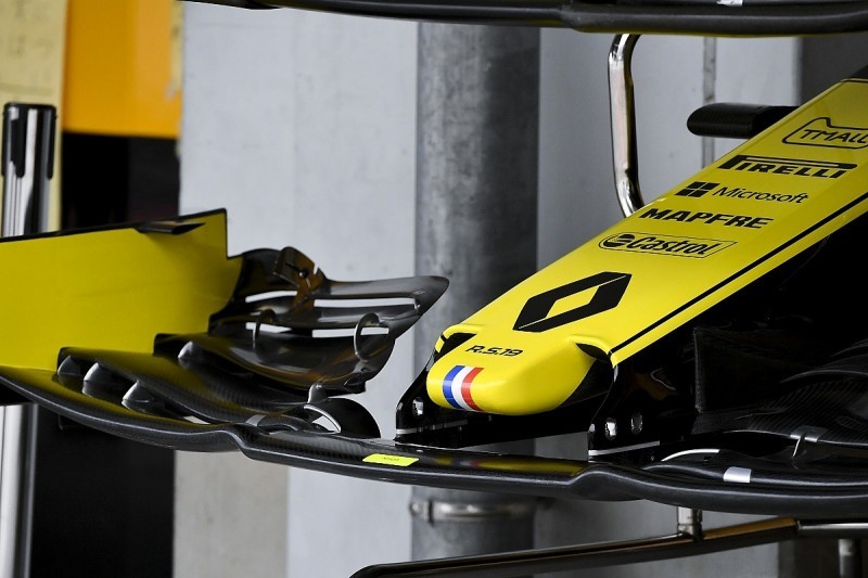
The Critical Role of the Front Wing
The front wing stands as a cornerstone of an F1 car’s aerodynamic performance. As the leading edge encountering airflow, it’s the first and arguably most critical part to influence how air moves around the entire vehicle.
A well-engineered front wing is not just about generating downforce directly; it’s about orchestrating airflow for the benefit of the car as a whole. A team that miscalculates the front wing design faces significant aerodynamic deficits that are difficult to compensate for elsewhere.
Beyond its own downforce creation, the front wing’s crucial task is to manage the turbulent air (wake) generated by the rotating front tires. By effectively diverting this wake, it paves the way for cleaner airflow to reach subsequent aerodynamic elements, most notably the floor and diffuser, boosting their efficiency.
Every contour and detail of the front wing is purposed to guide airflow around the front tires and away from the car’s underbody. The wingtips, specifically, generate vortices – swirling masses of air – that enhance airflow quality across the car, feeding the diffuser and mitigating drag from the front tires.
Endplates at the wing’s extremities play a vital role in preventing high-pressure air from spilling from the top surface to the underside, thereby maximizing downforce. They also contribute to directing airflow around the tires, while an attached footplate develops a vortex that further aids in diverting airflow.
Regulations in 2019 saw front wings widened to two meters, coupled with stricter design constraints aimed at promoting closer racing by reducing aerodynamic efficiency and wake management capabilities compared to previous designs.
Rear Wing and DRS: Enhancing Speed
Introduced in 2011, the Drag Reduction System (DRS) is a key component of the rear wing, designed to facilitate overtaking. This system allows a section of the rear wing to open on designated straights.
Upon activation, DRS lifts the leading edge of the wing flap by 70 millimeters, significantly increasing the slot gap and reducing the car’s frontal area. This reduction in drag translates directly into a boost in top speed, giving a pursuing car a potential advantage in overtaking.
The DRS mechanism involves an actuator mounted within the rear wing, connected to a linkage that enables near-instantaneous wing flap movement. Typically, DRS deactivates automatically when the driver releases the accelerator, allowing the airflow to reattach to the rear wing, and restoring full downforce for cornering and braking.
Prior to 2017 regulation changes, rear wings were taller and narrower. However, subsequent rules broadened and shortened them considerably, before further modifications in 2019 increased the rear wing’s height and flap size by 20mm. This latter change aimed to amplify DRS effectiveness and further encourage overtaking.
Race circuits feature designated DRS zones, typically located on longer straights, where drivers can activate the system. DRS usage is permitted when a driver is within one second of the car ahead, offering an opportunity to close the gap and attempt an overtake.
However, DRS is not a guaranteed pass. F1 history is replete with instances where drivers remain within DRS range for multiple laps without successfully overtaking. Effective DRS usage requires strategic considerations, including braking points and car positioning, to ensure a successful exit from the corner ahead of the overtaken car.
Sidepods: Packaging and Cooling Efficiency
Sidepods are crucial for the compact packaging of an F1 car, housing radiators and manifolds while minimizing aerodynamic drag. They represent a delicate balance of cooling requirements and aerodynamic efficiency.
The radiator inlets, positioned on each side of the car, must draw in sufficient air to cool the power unit effectively. Inadequate cooling can lead to engine overheating, performance degradation, and potential mechanical failure.
These inlets are meticulously designed to maximize cooling efficiency while maintaining minimal size. Their positioning is also critical, requiring placement in areas of clean, undisturbed airflow.
Deformable safety structures, located within the sidepods on either side of the cockpit, are vital safety elements.
Until 2016, deformable structures were positioned at the front of the sidepods and mandated to a fixed length for all cars. By 2018, a trend emerged among teams to decouple the deformable structure from the sidepod’s overall length, resulting in sidepods approximately 15cm shorter than the crash structure.
This design shift, aimed at drag reduction, positions the sidepod inlets further from the front axle, mitigating the disruptive airflow from the front tires and enhancing cooling efficiency.
Since the early 2000s, sidepods have incorporated a distinctive undercut at their base. This feature channels airflow over the floor’s upper surface in a streamlined manner, shortening its path and improving aerodynamic efficiency. This airflow can also act as a seal along the floor edges. Sidepods typically feature rearward openings to expel hot air, often flared outwards at circuits known for high ambient temperatures to improve cooling.
The Diffuser: Generating Downforce from Underneath
The diffuser, characterized by its flared opening at the rear of the car’s floor, is the primary component responsible for generating downforce from the vehicle’s underbody.
Airflow accelerates beneath the car, creating a low-pressure zone that generates downforce as the higher pressure air above pushes the car downwards. The diffuser’s expanding shape further accelerates this airflow, creating the lowest pressure area beneath the floor.
This accelerated airflow is drawn into the diffuser volume and expands, creating a transition from the high-speed underfloor flow to the ambient air velocity surrounding the car.
The diffuser’s shape is critical to prevent airflow separation as it exits from under the car, which can significantly diminish the floor’s overall effectiveness.
Turbulent airflow under the floor can also negatively impact performance, generating pockets of higher pressure that can destabilize the car’s underbody aerodynamics.
Like other aerodynamic parts, the diffuser area has undergone revisions in recent years. Regulations prior to 2017 restricted diffuser designs, but subsequent rule changes have allowed designers greater freedom to manipulate vertical strakes within the diffuser, the diffuser’s overall shape, and the area around the tires to optimize airflow.
Maximizing downforce gains from the diffuser is paramount. Teams must understand how airflow exits the diffuser area to minimize trailing drag. The diffuser’s edge features small winglets, and internal strakes create vortices to further enhance the low-pressure zone beneath the floor. Working in conjunction with the rear wing, the diffuser is instrumental in generating maximum possible downforce.
Suspension: Connecting Car and Track
The suspension system acts as the crucial link between an F1 car and its wheels, dictating the car’s response to track conditions and driver inputs. It is fundamental to both handling and aerodynamic performance.
Formula One regulations permit up to six structural members per wheel. Typically, this consists of two double wishbones, a pushrod or pullrod, and a steering arm or track rod, depending on whether it’s front or rear suspension.
Pullrod suspension is commonly used at the rear of F1 cars, while pushrod suspension was universally adopted at the front by all ten teams in 2019.
In a pushrod system, wheel movement upwards compresses a spring. A pullrod system operates in reverse. The choice between pushrod and pullrod is primarily dictated by packaging considerations within the car’s overall design.
Suspension setup is a primary area of focus for F1 teams. Extensive adjustments can be made to camber, toe, spring rates, ride height, and numerous other parameters to optimize car behavior for specific track characteristics.
Tires also function as part of the suspension system and are integral to suspension design. Different tire compounds possess varying properties, and suspension systems may exhibit better compatibility with certain compounds over others.
Suspension plays a significant role in aerodynamics. The steering lever is often integrated within the top wishbone to minimize aerodynamic disruption and improve airflow to downstream components. The lower wishbone is typically positioned high to bring the two wishbones closer, further optimizing airflow direction.
Suspension design has evolved dramatically throughout F1 history. McLaren’s 1969 M7C featured basic suspension with simple spring dampers and limited adjustability. By 1972, the M19C showcased more sophisticated inboard suspension connected via rockers, incorporating rising rate linkage systems. This advancement enabled engineers to customize suspension compression characteristics, allowing for more versatile car setups.
Modern F1 suspension design is incredibly advanced, serving not only its primary function of suspension but also playing a crucial role in optimizing aerodynamic performance, representing a significant leap in motorsport technology.