Welcome back to Gearhead 101 — a series designed to demystify car mechanics for everyone. If you’ve explored previous installments, you’re already familiar with how a car engine functions, the power transfer mechanisms of the drivetrain, and the intricacies of manual transmissions.
Today, we shift our focus to the unsung hero of modern driving: the automatic transmission. For many drivers, especially in regions like the United States, automatic transmissions are the standard. Have you ever pondered the magic behind effortless gear changes, happening seamlessly as you accelerate or decelerate?
Prepare to be amazed as we delve into the remarkable world of automatic transmissions – a pinnacle of mechanical and fluid engineering. Understanding its operation is truly awe-inspiring, especially considering its pre-computer-era invention.
Understanding the Transmission’s Role: A Quick Recap
Before dissecting the Parts Of An Automatic Transmission Car, let’s quickly revisit why any vehicle needs a transmission. As we covered in our engine basics guide, your car’s engine generates rotational power. This power must be transferred to the wheels to propel the vehicle, a task handled by the drivetrain, of which the transmission is a crucial component.
However, engines operate efficiently only within a specific rotational speed range. Too slow, and the car won’t move from a standstill; too fast, and engine damage is a risk. Therefore, we need a system to adjust the engine’s power output: multiplying it for demanding situations like starting or hill climbing, and reducing it for cruising or braking.
This is where the transmission steps in. It ensures the engine spins optimally while delivering the precise power needed at the wheels for any driving condition. Positioned between the engine and the rest of the drivetrain, it acts as a power management center for your vehicle.
We previously discussed how manual transmissions achieve this using gear ratios. By engaging different gear sizes, manual transmissions alter the power delivered to the wheels without drastically changing engine speed. If gear ratios are still unclear, reviewing the video from our previous discussion is highly recommended before proceeding, as this concept is fundamental to understanding transmissions.
Manual transmissions require driver input – using the clutch and gear lever to select gears. Automatic transmissions, however, automate this process through ingenious engineering, shifting gears based on driving conditions, leaving you to simply operate the gas and brake pedals. It’s truly automotive ingenuity at work.
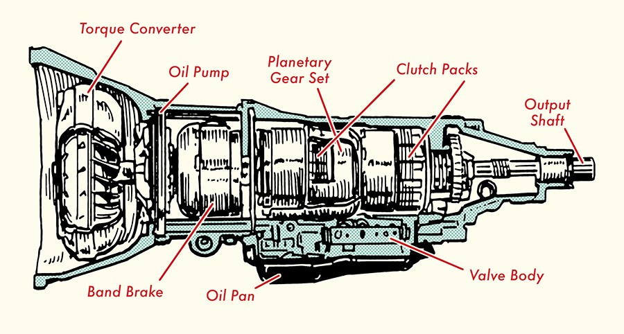
Exploring the Core Parts of an Automatic Transmission
Now that we’ve reaffirmed the transmission’s purpose – maintaining optimal engine speed while providing the necessary wheel power – let’s explore the specific parts that enable automatic gear changes. We will dissect the key parts of an automatic transmission car to understand their individual roles and collective function.
1. Transmission Casing (Bell Housing)
The transmission casing, often called the “bell housing” due to its bell-like shape, is the protective shell for all internal transmission components. Typically made of aluminum, this casing not only shields the delicate gears but also, in modern vehicles, houses sensors. These sensors are crucial for monitoring input rotational speed from the engine and output rotational speed directed to the rest of the vehicle.
2. Torque Converter
Ever wondered why your engine can be running while your car remains stationary in “Drive”? This is because the power flow from the engine to the transmission is initially disengaged. This disconnection, essential at idle, is achieved by the clutch in manual transmissions. But automatic transmissions, lacking a clutch pedal, employ a different mechanism: the torque converter.
This is where the fascinating mechanics of automatic transmissions truly begin. The torque converter, positioned between the engine and transmission, is a doughnut-shaped component nestled within the bell housing. It serves two primary torque-related functions:
- Power Transfer: It transmits power from the engine to the transmission’s input shaft.
- Torque Multiplication: It amplifies the engine’s torque output, especially during initial acceleration.
These functions are achieved through hydraulic power, utilizing the transmission fluid within the system. To understand this better, let’s break down the parts of a torque converter.
Delving into the Parts of a Torque Converter
Most modern vehicles feature a torque converter with four main components:
2.1. Pump (Impeller): The pump, resembling a bladed fan, has vanes radiating from its center. It’s directly mounted to the torque converter housing, which is, in turn, bolted to the engine’s flywheel. Consequently, the pump rotates at the same speed as the engine’s crankshaft. This synchronization is key to understanding the torque converter’s operation. The pump’s primary function is to “pump” transmission fluid outwards from its center towards the turbine.
2.2. Turbine: The turbine, also fan-like in appearance, resides inside the converter housing. It’s directly connected to the transmission’s input shaft but crucially, it’s not physically connected to the pump. This independence allows the turbine to rotate at a different speed than the pump, enabling the engine and drivetrain to operate at varying speeds. The turbine spins as it receives transmission fluid propelled by the pump. Its blades are designed to redirect the fluid towards the center of the turbine and back towards the pump, facilitating continuous fluid circulation.
2.3. Stator (Reactor): Positioned between the pump and turbine, the stator resembles a fan blade or propeller. It performs two critical functions:
a) **Efficient Fluid Return:** It optimizes the return of transmission fluid from the turbine back to the pump.
b) **Torque Multiplication:**  It amplifies engine torque during initial acceleration and reduces torque once the vehicle reaches cruising speed.

The stator achieves this through clever design. Its blades are angled to redirect fluid exiting the turbine in the same direction as the pump’s rotation.  Furthermore, the stator is connected to a fixed shaft via a one-way clutch, allowing rotation in only one direction. This ensures unidirectional fluid flow and prevents the stator from spinning until fluid speed from the turbine reaches a certain threshold. These design elements streamline the pump’s workload and increase fluid pressure, resulting in amplified torque at the turbine, which is then transferred to the transmission and the rest of the car.
2.4. Torque Converter Clutch (TCC): Due to fluid dynamics, some power is inevitably lost as transmission fluid travels from the pump to the turbine. This results in the turbine rotating slightly slower than the pump. While this speed difference is beneficial for torque multiplication during acceleration, it leads to energy inefficiency at cruising speeds. To counter this, modern torque converters incorporate a torque converter clutch connected to the turbine. Upon reaching a certain speed (typically around 45-50 mph), the TCC engages, locking the turbine to the pump, causing them to rotate at the same speed. A computer controls the engagement of the TCC, optimizing efficiency at higher speeds.
Let’s visualize the torque converter’s operation from a standstill to cruising speed:
- Idling: Engine is running, pump spins, sending fluid to the turbine. However, at idle speed, the turbine spins slowly, insufficient to deliver significant torque to the transmission.
- Acceleration: Pressing the gas pedal increases engine speed, accelerating the pump. Faster pump rotation increases fluid flow to the turbine, causing it to spin faster. Fluid from the turbine then hits the stator. Initially, the stator remains stationary due to low fluid speed.
- Torque Multiplication: As fluid passes through the stator blades, it’s redirected back towards the pump in the direction of pump rotation. This boosted fluid flow increases pump efficiency and fluid pressure. The fluid returns to the turbine with amplified torque, driving the turbine and subsequently the transmission with greater force, initiating vehicle movement.
- Cruising Speed: As the car accelerates, fluid pressure increases, eventually causing the stator to rotate. Stator rotation reduces torque multiplication. At cruising speed, less torque is needed to maintain momentum. The torque converter clutch engages, locking the turbine and pump to rotate at the same speed, eliminating fluid slippage and maximizing efficiency.
In essence, the torque converter enables power transmission from the engine to the transmission and dynamically adjusts torque multiplication for starting and acceleration. Now, let’s examine the components responsible for automatic gear shifting: planetary gears.
3. Planetary Gears
As vehicle speed increases, less torque is required to maintain momentum. Transmissions alter torque delivered to the wheels using gear ratios. Lower gear ratios provide higher torque, while higher ratios offer less torque and higher speed. Manual transmissions require manual gear selection to change these ratios. Automatic transmissions, however, achieve automatic ratio changes through planetary gear sets.
A planetary gear set is an ingenious system comprising three key parts:
- Sun Gear: The central gear in the set.
- Planet Gears (Pinions) and Carrier: Three or four smaller gears surrounding the sun gear, constantly meshed with it. These planet gears rotate on shafts mounted within the carrier. They not only spin on their axes but also orbit the sun gear.
- Ring Gear: The outer gear with internal teeth, surrounding the entire gear set and meshing with the planet gears.
A single planetary gear set can achieve reverse and multiple forward gear ratios, depending on which components are input, output, or held stationary. Let’s explore these configurations:
3.1. Gear Reduction: Sun Gear Input, Planetary Carrier Output, Ring Gear Stationary
In this scenario, the sun gear is the input, and the ring gear is held fixed. As the sun gear rotates, the planet gears rotate on their axes and “walk” around the inside of the stationary ring gear, but in the opposite direction of the sun gear. This forces the planet carrier to rotate in the same direction as the sun gear, making the carrier the output. This configuration creates a low gear ratio, meaning the input (sun gear) spins faster than the output (planet carrier). However, the planet carrier delivers significantly more torque than the sun gear input, ideal for starting the vehicle.
3.2. Direct Drive: Ring Gear Input, Planetary Carrier Output, Sun Gear Stationary
Here, the sun gear is held stationary, and the ring gear becomes the input. As the ring gear rotates, the meshed planet gears are forced to orbit the fixed sun gear, driving the planet carrier. The carrier rotates in the same direction as the ring gear and serves as the output. This configuration provides a slightly higher gear ratio than the previous one, but the input (ring gear) still spins faster than the output (planet carrier). This results in torque multiplication, suitable for acceleration or uphill driving.
3.3. Direct Drive (1:1 Ratio): Sun Gear and Ring Gear Input, Planetary Carrier Output
In this setup, both the sun gear and ring gear act as inputs, rotating at the same speed and direction. This locks the planet gears; they don’t spin on their individual shafts. Instead, the entire planetary gear set (sun gear, planet carrier, ring gear) rotates as a single unit at the same speed. Input and output torque are equal, known as direct drive, typically used for cruising around 45-50 mph.
3.4. Overdrive: Planetary Carrier Input, Ring Gear Output, Sun Gear Stationary
In overdrive, the sun gear is held stationary, and the planet carrier becomes the input. As the carrier rotates, the planet gears “walk” around the fixed sun gear, driving the ring gear faster. One carrier rotation results in more than one rotation of the ring gear in the same direction. This high gear ratio configuration, known as overdrive, provides higher output speed but less torque, ideal for highway driving at speeds of 60+ mph.
Automatic transmissions typically use multiple planetary gear sets in combination to achieve a wider range of gear ratios. Because planetary gears are constantly meshed, gear changes are seamless, unlike manual transmissions where gears are engaged and disengaged.
But how does an automatic transmission control which parts of the planetary gear system become input, output, or stationary to achieve these varying ratios? The answer lies in brake bands and clutches.
4. Brake Bands and Clutches
Brake bands are metal strips lined with friction material. They can tighten around components like the ring or sun gear to hold them stationary or loosen to allow rotation. Hydraulic pressure controls brake band operation.
Clutches, often multi-disc clutches in automatic transmissions, also play a crucial role. These consist of multiple interleaved metal and friction discs. When pressed together, the clutch engages, connecting components. Clutches can make a planetary gear component an input or hold it stationary, depending on their configuration within the system. Hydraulic, mechanical, and electrical systems work in concert to control clutch and brake band engagement, automating gear changes.
The intricate interplay of clutches and brake bands to control planetary gear components is complex and best understood visually. For a detailed visual explanation, this video is highly recommended:
[Insert Recommended Video Link Here – Original article suggests a video here, but no link provided. Find a suitable video on YouTube explaining automatic transmission operation visually and embed the link here if possible, or simply mention to search for one.]
How an Automatic Transmission Works: A System Overview
As you’ve seen, automatic transmissions are complex systems with numerous moving parts, integrating mechanical, fluid, and electrical engineering for smooth driving across various speeds. Let’s summarize the power flow:
- Engine to Torque Converter Pump: The engine powers the torque converter pump.
- Pump to Turbine: The pump transfers power to the turbine via transmission fluid.
- Turbine to Stator: Fluid from the turbine is directed back to the pump through the stator.
- Torque Multiplication by Stator: The stator amplifies fluid power, enabling the pump to send increased power back to the turbine, creating a vortex of power within the converter.
- Turbine to Transmission Input Shaft: The turbine connects to the transmission’s central input shaft. Turbine rotation drives the shaft, transferring power to the first planetary gear set.
- Planetary Gear Ratio Selection: Based on engaged multi-disc clutches and brake bands, power from the torque converter is directed to specific components of the planetary gear system (sun gear, planetary carrier, or ring gear), controlling their motion (input, output, or stationary).
- Power Output to Drivetrain: The resulting planetary gear configuration dictates the gear ratio, determining the power output sent to the rest of the drivetrain.
This overview simplifies a complex process involving sensors and valves for precise control, but it captures the fundamental operation of an automatic transmission. Visual aids are invaluable for grasping these mechanics fully. Watching a detailed video, especially after understanding these basics, is highly recommended.
Indeed, the automatic transmission is an engineering marvel. Now, as you experience gear shifts during your drive, you’ll have a deeper appreciation for the sophisticated mechanics working beneath the hood.
Explore Further
[Related Posts Link Placeholder – If there are related articles on carparteu.com, link them here]
Tags: [Automatic Transmission]([relevant tag link on carparteu.com if exists]) [Car Parts]([relevant tag link on carparteu.com if exists]) [Automotive Technology]([relevant tag link on carparteu.com if exists])