You may have come across the terms “OBD” or “OBDII” when reading about connected vehicles and Geotab’s GO device. These features are part of your car’s on-board computer system and have a history that’s not widely known. In this article, we’ll give you a comprehensive overview of OBDII and a timeline of its development, focusing on the crucial OBD2 connector.
Understanding OBD: On-Board Diagnostics
On-Board Diagnostics (OBD) refers to the automotive electronic system that provides vehicle self-diagnosis and reporting capabilities for repair technicians. An OBD system allows technicians to access subsystem information to monitor performance and diagnose repair needs efficiently.
OBD is the standard protocol used in most light-duty vehicles to retrieve vehicle diagnostic information. This information is generated by the Engine Control Units (ECUs), often referred to as the ‘brain’ or computer of your vehicle.
Why is the OBD Connector Important?
The OBD connector is a critical component for vehicle owners, mechanics, and fleet managers alike. It is essential for telematics and fleet management because it enables the measurement and management of vehicle health and driving behavior.
Thanks to the OBD connector and the system behind it, fleets and individuals can:
- Track wear and tear trends, identifying vehicle parts that degrade faster than others.
- Instantly diagnose vehicle issues before they escalate, facilitating proactive maintenance.
- Measure driving behavior, including speed, idling time, and much more, for performance optimization and safety.
Locating the OBD2 Port: Where to Find the Connector
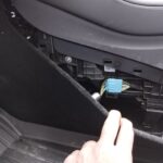
In a typical passenger vehicle, the OBD2 port is usually located on the underside of the dashboard on the driver’s side of the car. Depending on the vehicle type, the port may have a 16-pin, 6-pin, or 9-pin configuration, with the 16-pin being the most common for OBD2. Knowing the location of your OBD2 connector is the first step in accessing valuable vehicle data.
OBD vs. OBD2: What’s the Difference?
Simply put, OBD2 is the second generation of OBD or OBD I. OBD-I was initially connected externally to a car’s console, whereas OBD2 is integrated directly into the vehicle itself. The original OBD was in use until OBD2 was developed in the early 1990s to standardize and enhance diagnostic capabilities. The key difference lies in standardization and capability, with OBD2 offering a more comprehensive and universally accessible diagnostic interface through its standard OBD2 connector.
The Evolution of OBD2: A Historical Timeline
The history of on-board diagnostics dates back to the 1960s. Several organizations played a crucial role in laying the groundwork for the standard, including the California Air Resources Board (CARB), the Society of Automotive Engineers (SAE), the International Organization for Standardization (ISO), and the Environmental Protection Agency (EPA).
Before standardization, vehicle manufacturers developed their own proprietary systems. Each manufacturer’s tools, and sometimes even different models from the same manufacturer, had unique connector types and electronic interface requirements. They also used custom codes to report problems, making diagnostics complex and manufacturer-specific. The advent of the OBD2 connector and protocol aimed to resolve these inconsistencies.
Key Milestones in OBD History
1968 — Volkswagen introduces the first computer-based OBD system with scanning capability.
1978 — Datsun presents a simple OBD system with limited, non-standardized capabilities.
1979 — The Society of Automotive Engineers (SAE) recommends a standardized diagnostic connector and a set of diagnostic test signals, pushing for the standardization that would eventually lead to the OBD2 connector.
1980 — GM introduces a proprietary interface and protocol capable of providing engine diagnostics through an RS-232 interface, or more simply, by flashing the check engine light.
1988 — Standardization of on-board diagnostics gains momentum in the late 1980s following the 1988 SAE recommendation for a standard connector and diagnostic set, moving closer to the OBD2 connector standard.
1991 — The state of California mandates that all vehicles have some form of basic on-board diagnostics. This is known as OBD I.
1994 — California mandates that all vehicles sold in the state from 1996 onwards must have OBD as recommended by SAE, now termed OBDII, to facilitate widespread emissions testing. OBDII included a set of standardized Diagnostic Trouble Codes (DTCs), accessible via the OBD2 connector.
1996 — OBD-II becomes mandatory for all cars manufactured in the United States, making the OBD2 connector a standard feature.
2001 — EOBD (European version of OBD) becomes mandatory for all gasoline vehicles in the European Union, mirroring the OBD2 connector’s role in Europe.
2003 — EOBD becomes mandatory for all diesel vehicles in the EU, extending the reach of standardized diagnostics.
2008 — Starting in 2008, all vehicles in the United States are required to implement OBDII via a Controller Area Network, as specified in ISO standard 15765-4, further refining the communication through the OBD2 connector.
Image: A close-up view of an OBD II port, typically located beneath the dashboard of a vehicle.
Data Access Through OBD2 Connector: What Can You Learn?
The OBD2 system, accessed via the OBD2 connector, provides access to both status information and Diagnostic Trouble Codes (DTCs) for:
- Powertrain (engine and transmission)
- Emission control systems
Furthermore, the following vehicle information can be accessed through the OBD2 connector:
- Vehicle Identification Number (VIN)
- Calibration Identification Number
- Ignition counter
- Emission control system counters
When you take your car to a service shop, a mechanic can connect a scan tool to the OBD port using the OBD2 connector, read fault codes, and pinpoint the problem. This capability means mechanics can accurately diagnose malfunctions, quickly inspect the vehicle, and address issues before they become major problems.
Examples of Data Accessed via OBD2 Connector:
Mode 1 (Vehicle Information):
- PID 12 — Engine RPM
- PID 13 — Vehicle Speed
Mode 3 (Fault Codes: P= Powertrain, C= Chassis, B= Body, U= Network):
- P0201 — Injector Circuit Malfunction – Cylinder 1
- P0217 — Engine Overtemperature Condition
- P0219 — Engine Overspeed Condition
- C0128 — Brake Fluid Low Circuit
- C0710 — Steering Position Malfunction
- B1671 — Battery Module Voltage Out of Range
- U2021 — Invalid/Faulty Data Received
OBD and Telematics: Connecting for Vehicle Insights
The presence of the OBD2 connector enables telematics devices to seamlessly process information such as engine RPM, vehicle speed, fault codes, fuel consumption, and much more. The telematics device can use this data to determine trip start and end times, over-revving, speeding, excessive idling, fuel usage, etc. All of this information is then uploaded to a software interface, allowing fleet management teams and vehicle owners to monitor vehicle usage and performance effectively, all thanks to the data accessed through the OBD2 connector.
Given the multitude of OBD protocols, not all telematics solutions are designed to work with every type of vehicle currently on the road. Geotab telematics overcomes this challenge by translating diagnostic codes from various makes and models, including electric vehicles. This broad compatibility is essential for leveraging the full potential of the OBD2 connector across diverse vehicle fleets.
With the OBD-II port and its standard OBD2 connector, connecting a fleet tracking solution to your vehicle is quick and easy. For Geotab, setup can be completed in under five minutes.
If your vehicle or truck does not have a standard OBDII port, an adapter can be used instead. In any case, the installation process remains fast and does not require any special tools or professional installer assistance, highlighting the versatility of the OBD2 connector system.
Image: A mechanic using an OBD scanner connected to the OBD2 port of a vehicle to diagnose potential issues.
What is WWH-OBD? Expanding Diagnostic Horizons
WWH-OBD stands for World Wide Harmonized On-Board Diagnostics. It is an international standard used for vehicle diagnostics, implemented by the United Nations as part of the Global Technical Regulation (GTR) mandate. WWH-OBD encompasses the monitoring of vehicle data, including emissions output and engine fault codes, enhancing the capabilities beyond the traditional OBD2 connector.
Advantages of WWH-OBD: Enhanced Data and Diagnostics
Transitioning to WWH-OBD offers several technical advantages:
Access to More Data Types
Currently, OBDII PIDs (Parameter IDs) used in Mode 1 are only one byte, meaning only up to 255 unique data types are available. Expanding PIDs, as facilitated by WWH-OBD, could also apply to other OBD-II modes transitioned to WWH through UDS modes. Adopting WWH standards allows for more data and provides the scalability for future expansion, increasing the information available through the OBD system and connector.
More Detailed Fault Information
Another advantage of WWH-OBD is the expanded fault information. Currently, OBDII uses a two-byte Diagnostic Trouble Code (DTC) to indicate when a fault has occurred (e.g., P0070 indicates that the ambient air temperature sensor “A” has a general electrical fault).
Unified Diagnostic Services (UDS) expands the 2-byte DTC into a 3-byte DTC, where the third byte indicates the “failure mode.” This failure mode is similar to the Failure Mode Indicator (FMI) used in the J1939 protocol. For example, previously in OBDII, you might have the following five faults:
- P0070 Ambient Air Temperature Sensor Circuit
- P0071 Ambient Air Temperature Sensor Range/Performance
- P0072 Ambient Air Temperature Sensor Circuit Low Input
- P0073 Ambient Air Temperature Sensor Circuit High Input
- P0074 Ambient Air Temperature Sensor Circuit Intermittent
With WWH-OBD, these are all consolidated into one code P0070, with 5 different failure modes indicated in the third byte of the DTC. For example, P0071 now becomes P0070-1C.
WWH-OBD also offers more fault information, such as severity/class and status. Severity indicates how quickly the fault should be reviewed, while the fault class indicates which group the fault belongs to according to GTR specifications. Additionally, fault status indicates whether it is pending, confirmed, or if the test for this fault has been completed in the current driving cycle, providing a richer diagnostic picture accessed through the OBD system.
In summary, WWH-OBD expands the current OBDII framework to offer even more diagnostic information to the user, further leveraging the capability of the OBD2 connector.
Geotab’s WWH-OBD Support: Future-Proofing Diagnostics
Geotab has already implemented the WWH protocol in our firmware. Geotab employs a sophisticated protocol detection system, where we safely examine what is available in the vehicle to determine if OBD-II or WWH-OBD is available (in some cases, both are). This forward-thinking approach ensures compatibility with evolving diagnostic standards, enhancing the long-term value of OBD2 connector-based telematics solutions.
At Geotab, we are constantly improving our firmware to expand the information our customers receive. We have already begun supporting 3-byte DTC information and continue to add more fault information generated in vehicles. When new information becomes available through OBDII or WWH-OBD (such as a new PID or fault data), or if a new protocol is implemented in the vehicle, Geotab prioritizes quickly and accurately adding it to the firmware. We then immediately send the new firmware to our units over the cloud so that our customers always get the most benefit from their devices, ensuring that the OBD2 connector continues to provide access to the latest diagnostic advancements.
Growing Beyond OBDII: UDS and the Future of Diagnostics
OBDII contains 10 standard modes to obtain the diagnostic information required by emissions standards. The challenge is that these 10 modes have proven to be insufficient for the increasing complexity of vehicle systems.
Over the years since the implementation of OBDII, several UDS modes have been developed to enrich the available data. Each vehicle manufacturer uses its own PIDs and implements them using additional UDS modes. Information not required through OBDII data (such as odometer and seat belt usage) became available through UDS modes.
UDS actually contains more than 20 additional modes on top of the current 10 standard modes available through OBDII, meaning UDS has a wealth of more available information. But that’s where WWH-OBD comes in, seeking to incorporate UDS modes with OBDII to enrich the data available for diagnostics, while still maintaining a standardized process, building upon the foundation of the OBD2 connector.
Conclusion: The Enduring Importance of the OBD2 Connector
In the growing world of IoT, the OBD port and its OBD2 connector remain crucial for vehicle health, safety, and sustainability. While the number and variety of connected devices for vehicles increase, not all devices provide and track the same information. Furthermore, compatibility and security can vary from device to device.
Given the multitude of OBD protocols, not all telematics solutions are designed to work with every type of vehicle currently on the road. Good telematics solutions must be able to understand and translate a comprehensive set of vehicle diagnostic codes, ensuring that the OBD2 connector can be effectively utilized across a wide range of vehicles for optimal fleet management and vehicle maintenance.