PLEASE NOTE: This blog post is a conceptual overview of creating Raspberry Pi OBD2 gauges. For technical details on setup, refer to the official obdPi documentation here.
Introduction
Back in the summer of 2015, my quest for a boost gauge for my Fiesta ST led me down an unexpected path. While watching a review of the 2016 Subaru WRX, I was intrigued by its central multi-function display showcasing real-time data like boost pressure and fuel economy. This feature, alongside the functionality of the COBB AccessPort, sparked an idea: why not build my own custom gauge display using a spare Raspberry Pi?
Inspired by the WRX’s integrated display and the versatility of devices like the AccessPort, I envisioned a DIY project that would not only be a practical addition to my car but also a fantastic learning experience. My initial plan involved tackling several key aspects:
- Learning Python programming to control the system and display.
- Wiring a 16×2 OLED screen to visually present the data.
- Establishing Bluetooth communication to retrieve OBD-II data from my car wirelessly.
- Implementing an ignition-dependent power supply for seamless integration.
- Configuring a lightweight, headless Raspbian OS for efficient operation.
Sharing my nascent idea on online forums and boards garnered valuable feedback, including suggestions like using the Torque Pro app. While Torque Pro is feature-rich, I found it somewhat cluttered for my taste. Moreover, using my phone as a display would mean windshield mounting, potentially obstructing my view, and tying up my device which I often use for calls and music while driving.
Another suggestion was to use a pressure transducer directly interfaced with the Raspberry Pi for a digital boost display. While feasible, my ambition was to tap into the wealth of data available via the OBD-II interface – far beyond just boost pressure. The OBD-II port offers standardized access to a wide array of vehicle diagnostics and performance metrics.
Researching Existing Raspberry Pi OBD2 Gauge Projects
To ensure I wasn’t completely reinventing the wheel, I delved into researching existing in-car computer projects that displayed vehicle data. CowFish Studios’ obdPi project emerged as a prominent and well-documented example. However, their approach utilized a multi-color LCD and an older Python OBD-II library, which I aimed to improve upon.
CarBerry’s system was another promising option, boasting a polished and seemingly high-quality OBD2 carputer. Unfortunately, it was also designed for LCD head unit output and, considering shipping and accessories, exceeded my project budget.
Several other projects surfaced during my research, but many appeared to be either outdated, poorly documented, or lacked crucial details. Ultimately, I decided to draw inspiration from the best aspects of these projects, using them as a foundation while forging my own path to create a unique and improved Raspberry Pi OBD2 gauge system.
Essential Supplies for Your DIY Car Gauge
As I embarked on this project, the Raspberry Pi 2 had just been released. I opted for a Vilros Raspberry Pi 2 Ultimate Starter Kit (the link now directs to a newer Pi 3 kit). Being new to electronics wiring, I anticipated that this kit would provide nearly everything I needed to get started with Raspberry Pi GPIO and basic circuitry.
Beyond the starter kit, I also acquired the following components specifically for the Raspberry Pi Obd2 Gauges project:
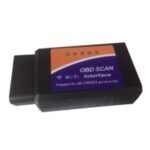
NOTE: When purchasing an OBD-II Bluetooth adapter, invest in a reputable brand. My initial cheap knock-off adapter proved to be unreliable and was replaced.
Wiring the OLED Display for Clear Visibility
Having grasped the fundamentals of Raspberry Pi wiring through tutorials included in the starter kit, I decided to directly tackle wiring an OLED display.
While numerous LCD options are available for the Raspberry Pi, I chose the Adafruit 16×2 character OLED display for several compelling reasons. Firstly, its OLED nature simplifies wiring by eliminating the need for a backlight. Secondly, OLEDs offer superior readability in direct sunlight, crucial for an in-car display. Finally, the display’s color closely matched the factory gauge screen in my Fiesta ST, aiming for a seamless, OEM-like aesthetic.
The primary challenge with this particular OLED display was the scarcity of readily available wiring documentation. While Adafruit provides excellent tutorials for their LCDs, support for this specific OLED model seemed limited. Undeterred, I proceeded, using generic LCD wiring guides as a starting point.
Unfortunately, my initial wiring attempt resulted in a fried display. A quick Amazon exchange later, a replacement display was on its way for a second attempt. While awaiting the replacement, I discovered a helpful raspberrypi.org forum post specifically addressing wiring this OLED display. Following the forum’s suggestions proved much more successful the second time around.
For a detailed step-by-step guide and wiring diagrams for connecting an OLED display to your Raspberry Pi, please consult the comprehensive obdPi documentation.
Establishing Bluetooth and Serial Communication
With a functional display in place, the next hurdle was configuring Raspbian to communicate with the Bluetooth OBD-II adapter.
This phase involved considerable trial and error, as I struggled to find specific documentation for my setup: a Bluetooth OBD-II adapter communicating with a Bluetooth USB adapter connected to a headless Raspbian system running a Python script. However, after persistent effort, I achieved a working configuration. (Refer to the “Bluetooth Setup” and “Serial Connection” sections of the documentation for in-depth instructions.)
In essence, the Bluetooth OBD-II adapter pairs with the Bluetooth USB adapter through the Raspberry Pi’s Bluetooth utility. This Bluetooth connection is then mapped to a virtual serial port, accessible within Python using the pyserial library.
Finally, by adding commands to the /etc/rc.local startup file, I automated this pairing process to occur upon system boot, ensuring seamless operation every time the car is started.
Crafting Python Scripts for OBD2 Data Retrieval
With both the display and communication channels operational, the next logical step was to develop Python scripts to fetch OBD-II data from the car’s computer and display it.
I initially (and somewhat optimistically) started by trying to understand the intricacies of the OBD-II interface directly. While I made some progress, my initial scripts were rudimentary and inefficient.
Realizing the need for a more robust and elegant solution, I discovered the python-OBD library!
python-OBD is exceptionally well-structured, continuously updated with new features, and boasts a responsive developer who actively addresses user requests and questions.
Leveraging the power of python-OBD, I rapidly developed a functional script that successfully output OBD-II data to the OLED display.
As the flashing display indicates, the code was still in its early stages of development, but it marked significant progress. The next major challenge to tackle was reliably powering the Raspberry Pi within the car environment.
Powering the Raspberry Pi In-Car: Overcoming Power Supply Challenges
During my Raspberry Pi research, the name Mausberry Circuits frequently appeared in power supply tutorials. I ordered one of their 2A car-specific power supplies, hoping for a straightforward power solution.
Mausberry car switches are designed to utilize both ignition-dependent and always-on 12V car power sources. They are engineered to power the Raspberry Pi when the car is on and initiate a safe shutdown sequence when the ignition is turned off. In theory, these switches seemed ideally suited for this Raspberry Pi OBD2 gauge project.
However, after installing a Mausberry car switch, I encountered immediate problems. I wired the switch into my car’s fuse box using fuse taps.
Initial testing seemed promising, but after approximately 30 seconds of operation, the switch would abruptly cut power to the Pi, forcing a hard shutdown. I meticulously tested various fuse combinations, wiring configurations, USB cables, and even direct battery connections, all to no avail. Suspecting a faulty switch, I used a multimeter (after sacrificing a USB cable for testing leads) and confirmed that the Mausberry switch itself appeared to be the source of the issue.
I reached out to Mausberry support but received no response after weeks of waiting. Giving them the benefit of the doubt, I ordered a second switch, this time the 3A version. After another anxious wait, the new switch arrived a few weeks later.
Unfortunately, the replacement switch exhibited the same power cut-off issue. Further testing with different cables, power sources, and fuse configurations yielded no improvement.
At this point, frustration was mounting, exacerbated by the lack of communication from Mausberry. Fortunately, I discovered an alternative solution: the UPS PIco from Pimodules. I contacted Pimodules directly, inquiring about the UPS PIco’s suitability for in-car use. They responded promptly with confidence in its application, so I placed an order immediately.
Due to international shipping and customs, delivery took some time. However, upon arrival, the UPS PIco impressed me right out of the box.
The setup guide was exceptionally clear and easy to follow.
The UPS PIco utilizes a small 450mAh LiPo battery to provide backup power to the Pi in case of power loss (i.e., when the car is turned off). It then uses scripts to initiate a safe shutdown after a short period of battery power. The UPS PIco also offers optional cooling fan integration and provides easy access to voltage and battery level information via status LEDs that clearly indicate whether it’s running on 5V or battery power.
Thanks to the excellent documentation, I had the UPS PIco configured and operating flawlessly in under an hour. After months of power supply frustrations, I finally had a fully functional and reliable power solution, completing the core system for my Raspberry Pi OBD2 gauges project!
Installation and Testing in the Car
With the Raspberry Pi OBD2 gauge system fully assembled and tested on the bench, it was time for in-car integration.
Since the UPS PIco replaced the Mausberry circuit’s voltage converter, I needed an alternative to step down the car’s 12V power to the Raspberry Pi’s required 5V. I found this voltage regulator on Amazon and wired it into the system.
With everything prepared, I first routed the OLED display cable through the dashboard from the glovebox.
I decided to position the OLED display just below the instrument cluster. This location seemed easiest for cable routing and provided a clean, integrated look.
Finally, the moment of truth: a test drive!
Success! The entire system worked as expected. I left it installed for several weeks of real-world testing and, while there were minor software bugs to iron out, encountered no major hardware issues. The Raspberry Pi OBD2 gauges were functional and providing valuable data.
Crafting an OLED Housing for a Finished Look
With the core functionality achieved, I turned my attention to the aesthetics of the Raspberry Pi OBD2 gauge installation.
The exposed green OLED PCB against the black dashboard looked somewhat unfinished. I decided to fabricate a simple housing from perspex plastic sourced from a local home improvement store. This also justified finally purchasing a Dremel tool!
Future Enhancements for the Raspberry Pi OBD2 Gauge Project
This entire project has been an invaluable learning experience. What began as a casual idea evolved into one of the most challenging and time-consuming projects I’ve ever undertaken. There were countless late nights in the garage, enduring both freezing and sweltering temperatures, wrestling with Python code that seemed unnecessarily complex at times.
A heartfelt thank you to my girlfriend for her incredible patience and support. She never questioned the piles of electronics and wires accumulating around the house (though she did jokingly mention something about “bomb-making” once), and consistently provided motivation and encouragement.
To some, this Raspberry Pi OBD2 gauge project might appear trivial or straightforward. However, for me, it became a powerful lesson in perseverance and the immense satisfaction derived from sticking with a project, even through numerous setbacks. The final result is always worth the effort.
I am genuinely excited about the future possibilities of this project and have already compiled an extensive list of potential improvements and expansions.
Thank you for taking the time to read about my DIY Raspberry Pi OBD2 gauges journey!
[