Working on your car’s diagnostics or electronics often involves the OBD2 port. If you’re looking to create a custom connection, understanding the components, especially the male pins in an OBD2 connector, is crucial. This guide will walk you through creating a simple OBD2 connector harness, focusing on selecting the correct male pin size and other essential details.
Understanding OBD2 Connector Pin Size for DIY Projects
When diving into DIY OBD2 projects, one of the first questions you might have is, “what size male pin to use on an obd2?”. The answer isn’t just about physical dimensions; it’s also about electrical conductivity and compatibility with your wiring. OBD2 connectors use standard male pins designed to mate with the female pins in your vehicle’s OBD2 port. These pins are designed to carry various signals and power, so choosing the right size is essential for a reliable connection.
For most standard OBD2 DIY projects, you’ll be working with pins designed for specific wire gauges. Typically, OBD2 connectors utilize pins that accommodate wire sizes ranging from 22AWG to 16AWG. This range is suitable for the low-current data and power signals transmitted through the OBD2 port. Using the correct pin size ensures a secure mechanical and electrical connection, preventing issues like signal loss or intermittent connectivity.
DIY OBD2 Connector Harness: Step-by-Step Guide
This guide is adapted from a DIY approach to creating a basic OBD2 harness. It’s important to note that this is for informational purposes, and you should proceed at your own risk. Incorrect wiring or component selection can potentially damage your vehicle’s electronics. Always double-check your connections and consult professional resources if you’re unsure.
Tools and Parts You’ll Need
Before you begin, gather the necessary tools and parts:
- Wire strippers/cutters
- Needle-nose pliers
- Molex crimping tool (recommended for a professional finish, but pliers can be used)
- Soldering iron and solder (optional, but recommended for enhanced connection reliability)
- 4-Pin Connector (Link to example part; ensure pin/wire size compatibility: 22-16AWG; insulation/seal size: 1.3-1.7mm)
- OBD-II Cable (Link to example part)
If you have spare wire, you can purchase a female OBD-II connector separately and wire it directly, ensuring you choose a 4-pin connector with pins compatible with your wire gauge.
Wiring and Pin Selection
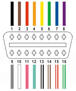
For this basic harness, we’ll use only four wires from the OBD2 connector, focusing on essential functions:
- Pin 4: Chassis Ground (typically black or orange wire)
- Pin 6: CAN High (J-2284) (typically green wire)
- Pin 14: CAN Low (J-2284) (typically brown with white stripe wire)
- Pin 16: Battery Power (typically green with white stripe wire)
Step 1: Prepare the OBD2 Cable Wires
Start by separating the four necessary wires from the OBD2 cable. Carefully remove the outer sheath and shielding to access the individual wires. Bundle the remaining unused wires and secure them to keep them out of the way.
Step 2: Prepare the Wire Ends and Seals
The wires in the OBD2 cable are often 26AWG, which might be smaller than the pins in your 4-pin connector designed for 22-16AWG. To ensure a secure fit, strip about 3/8″ of insulation from the end of each of the four wires. Fold the exposed wire back onto itself and twist to effectively thicken it, making it more compatible with the 22-16AWG pins. Slide a rubber seal from the 4-pin connector kit onto each wire.
Step 3: Attach Wires to the Male Pins
Take one of the male pins from your 4-pin connector kit. Notice the two sets of prongs on the pin. The front prongs are for securing the wire, and the rear prongs are for the rubber seal. Insert the prepared wire into the front set of prongs.
Step 4: Solder the Wire to the Pin (Recommended)
For a robust and reliable connection, soldering the wire to the pin is highly recommended, especially when dealing with thinner wires. Solder the wire to the front prongs of the pin. If you’re new to soldering, online resources can provide helpful tips and techniques.
Step 5: Crimp the Pin Connectors
If you have a Molex crimping tool, use it to crimp the front prongs of the pin securely around the wire. If you don’t have this tool, needle-nose pliers can be used carefully. Fold one prong over the wire at a time, ensuring a tight crimp. For added security, you can slightly crush the crimped prongs further with pliers.
Step 6: Crimp the Seal Prongs
Slide the rubber seal up the wire until it sits between the rear set of prongs on the pin. Use the same crimping technique (with a crimping tool or needle-nose pliers) to fold these prongs over the rubber seal. This provides strain relief and environmental protection.
Step 7: Twist Wire Pairs (Recommended)
While not strictly necessary, twisting wire pairs is often recommended in CAN bus systems to reduce electromagnetic interference. Twist the following wire pairs together:
- Pin 4 (orange/ground) and Pin 16 (green w/white stripe/power)
- Pin 6 (green/CAN High) and Pin 14 (brown w/white stripe/CAN Low)
Step 8: Insert Pins into the 4-Pin Connector Housing
Insert the pins into the 4-pin connector housing in the correct orientation. The typical pinout is as follows (refer to your connector’s documentation for exact positions):
- Slot A: Pin 14 (brown w/white stripe/CAN Low)
- Slot B: Pin 6 (green/CAN High)
- Slot C: Pin 16 (green w/white stripe/power)
- Slot D: Pin 4 (orange/ground)
Push each pin into the connector housing from the rear until you hear a click, indicating it is locked in place. Use needle-nose pliers to gently pull the wire to ensure the pin is securely seated.
Conclusion
You have now created a basic custom OBD2 connector harness. Understanding “what size male pin to use on an obd2” is crucial for ensuring proper electrical and mechanical connection in your DIY automotive projects. By using the correct pins for your wire gauge and carefully following these steps, you can create a functional and reliable OBD2 connector for diagnostic or electronic integration purposes. Remember to always double-check your wiring and proceed with caution when working with vehicle electronics.