Looking to dive into OBD2 monitoring but unsure which parameters are most valuable?
This guide, crafted by carparteu.com’s auto repair experts, goes beyond a basic OBD2 intro. We’ll pinpoint the most useful OBD2 Parameter IDs (PIDs) to monitor, empowering you to gain insightful data from your vehicle’s diagnostics system.
Building upon the foundation of a practical OBD2 introduction, this article is enhanced for English-speaking users seeking actionable insights. We’ll explore how to effectively utilize OBD2 PIDs for vehicle health monitoring, performance analysis, and diagnostics, making it the ultimate resource for understanding OBD2 data.
You can also check out our OBD2 intro video above – or get the PDF guide to CAN bus
In this article
Author: Martin Falch (updated January 2025)
Download as PDF
Understanding OBD2 and its Monitoring Potential
OBD2, or On-Board Diagnostics II, is your car’s built-in health monitoring system. It’s a standardized protocol enabling access to Diagnostic Trouble Codes (DTCs) and real-time vehicle data through the OBD2 connector.
You’re likely familiar with OBD2 through the check engine light on your dashboard. This light signals an issue detected by your car’s self-diagnostic system. Mechanics use OBD2 scanners connected to the 16-pin OBD2 port, typically located near the steering wheel, to read these codes and diagnose problems. These scanners send ‘OBD2 requests’ and receive ‘OBD2 responses’ containing data like speed, fuel level, and DTCs, streamlining the troubleshooting process.
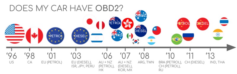
OBD2 Compatibility: Is Your Car Supported?
Most likely, yes!
The vast majority of modern gasoline and diesel cars (non-electric) are OBD2 compliant and utilize CAN bus communication. However, older vehicles might have a 16-pin connector that doesn’t actually support OBD2. Compliance often depends on the vehicle’s purchase location and year:
A Brief History of OBD2 and Emission Control
OBD2 originated in California, driven by the California Air Resources Board (CARB) mandate for OBD in all new cars from 1991 onwards for emission monitoring.
The Society of Automotive Engineers (SAE) standardized OBD2, defining DTCs and the OBD connector across manufacturers with SAE J1962.
OBD2 adoption expanded progressively:
- 1996: OBD2 became mandatory in the USA for cars and light trucks.
- 2001: Required in the EU for gasoline vehicles.
- 2003: EU mandate extended to diesel vehicles (EOBD).
- 2005: OBD2 required for medium-duty vehicles in the US.
- 2008: US vehicles mandated to use ISO 15765-4 (CAN) for OBD2 communication.
- 2010: OBD2 became mandatory for heavy-duty vehicles in the US.
The Future of OBD2: Trends and Challenges
OBD2’s role is evolving. Here are key trends to consider:
Initially designed for emissions control, legislated OBD2 isn’t mandatory for electric vehicles (EVs). Consequently, most modern EVs don’t support standard OBD2 requests, opting for OEM-specific UDS communication. This makes data extraction challenging without reverse engineering efforts – as seen in case studies for EVs like Tesla, Hyundai/Kia, Nissan, and VW/Skoda.
Limitations in data richness and lower-layer protocols have spurred development of alternatives like WWH-OBD (World Wide Harmonized OBD) and OBDonUDS (OBD on UDS). These aim to improve OBD communication using the UDS protocol. Learn more in our UDS protocol introduction.
In our connected world, manual emission checks via OBD2 feel outdated. The proposed solution? OBD3 – integrating telematics into vehicles.
OBD3 envisions a small radio transponder in cars, transmitting the Vehicle Identification Number (VIN) and DTCs via WiFi to a central server for automated checks. Devices like the CANedge2 WiFi CAN logger and CANedge3 3G/4G CAN logger already facilitate CAN/OBD2 data transfer via WiFi/cellular. While convenient and cost-saving, privacy concerns pose political hurdles.
OBD2 was initially intended for in-shop emission controls. Today, third parties widely use OBD2 for real-time data via OBD2 dongles, CAN loggers and more. However, the German car industry seeks to restrict this:
“OBD has been designed to service cars in repair shops. In no way has it been intended to allow third parties to build a form of data-driven economy on the access through this interface” – Christoph Grote, SVP Electronics, BMW (2017)
The proposal involves disabling OBD2 functionality during driving, centralizing data collection with manufacturers controlling ‘automotive big data’. Justifications include security (reducing car hacking risks), though many perceive this as a commercial maneuver (Navixy blog on OBD trackers). Whether this trend takes hold remains to be seen, but it could significantly disrupt the OBD2 third-party service market.
Enhance Your CAN Bus Expertise
Become a CAN bus expert with our comprehensive guide!
Access 12 ‘simple intros’ in our 160+ page PDF:
Download now
OBD2 Standards: Connector, Protocols, and PIDs
On-board diagnostics, OBD2, is a higher-layer protocol, similar to a language, while CAN is the communication method, akin to a phone line. OBD2 is comparable to other CAN-based higher-layer protocols like J1939, CANopen, and NMEA 2000.
OBD2 standards define the connector, lower-layer protocols, and crucially, OBD2 Parameter IDs (PIDs), among other specifications.
These standards can be viewed within a 7-layer OSI model. Notably, both SAE and ISO standards cover multiple layers, reflecting US (SAE) and EU (ISO) OBD standards. Many are technically similar, such as SAE J1979 vs. ISO 15031-5 and SAE J1962 vs. ISO 15031-3.
The OBD2 Connector [SAE J1962 / ISO 15031-3]
The 16-pin OBD2 connector, standardized in SAE J1962 / ISO 15031-3, provides easy access to vehicle data. The illustration above shows a Type A OBD2 pin connector (Data Link Connector, DLC).
Key points about the OBD2 connector:
- Usually near the steering wheel, possibly hidden.
- Pin 16 provides battery power, even when ignition is off.
- OBD2 pinout varies depending on communication protocol.
- CAN bus is the most common lower-layer protocol, typically using pins 6 (CAN-H) and 14 (CAN-L).
OBD2 Connector Types: A vs. B
You might encounter Type A and Type B OBD2 connectors. Type A is standard in cars, while Type B is common in medium and heavy-duty vehicles.
While pinouts are similar, Type A and B differ in power supply (12V vs. 24V) and often baud rate (cars typically 500K, heavy-duty vehicles 250K, sometimes 500K).
Type B connectors have a central interrupted groove, making Type B OBD2 adapter cables compatible with both Type A and B sockets, whereas Type A adapters only fit Type A sockets.
OBD2 and CAN Bus [ISO 15765-4]: The Communication Foundation
Since 2008, ISO 15765 mandates CAN bus as the lower-layer protocol for OBD2 in US vehicles.
ISO 15765-4 (Diagnostics over CAN or DoCAN) specifies restrictions on the CAN standard (ISO 11898), standardizing the CAN interface for diagnostic equipment at the physical, data link, and network layers:
- CAN bus bit-rate: 250K or 500K.
- CAN IDs: 11-bit or 29-bit.
- Specific CAN IDs for OBD requests/responses.
- Diagnostic CAN frame data length: 8 bytes.
- OBD2 adapter cable limit: 5 meters.
OBD2 CAN Identifiers (11-bit, 29-bit)
OBD2 communication is request/response based.
Most cars use 11-bit CAN IDs for OBD2. The ‘Functional Addressing’ ID is 0x7DF, querying all OBD2-compatible ECUs for data on the requested parameter (ISO 15765-4). CAN IDs 0x7E0-0x7E7 are for ‘Physical Addressing’ requests to specific ECUs (less common).
ECU responses use 11-bit IDs 0x7E8-0x7EF. 0x7E8 (ECM – Engine Control Module) and 0x7E9 (TCM – Transmission Control Module) are common response IDs.
Some vehicles (vans, light/medium/heavy-duty) use 29-bit CAN identifiers for OBD2.
The ‘Functional Addressing’ CAN ID here is 0x18DB33F1.
Responses use CAN IDs 0x18DAF100 to 0x18DAF1FF (e.g., 18DAF110, 18DAF11E), sometimes shown as ‘J1939 PGN’ PGN 0xDA00 (55808), marked ‘Reserved for ISO 15765-2’ in J1939-71.
OBD2 vs. Proprietary CAN Protocols: What’s the Difference?
Vehicle ECUs operate using OEM-specific CAN protocols, not OBD2. OEMs develop proprietary CAN protocols specific to brand, model, and year. This OEM-specific data is generally inaccessible without reverse engineering (CAN bus sniffing).
Connecting a CAN bus data logger to the OBD2 port might capture OEM-specific CAN data (typically broadcast at 1000-2000 frames/second). However, newer vehicles often use a ‘gateway’ to block OEM CAN data access via the OBD2 port, allowing only OBD2 communication.
Think of OBD2 as a supplementary higher-layer protocol alongside the OEM-specific protocol.
Bit-rate and ID Validation for Reliable Communication
OBD2 can use two bit-rates (250K, 500K) and two CAN ID lengths (11-bit, 29-bit), resulting in four combinations. Modern cars commonly use 500K and 11-bit IDs. Tools should systematically verify this.
ISO 15765-4 recommends an initialization sequence (flowchart below) to determine the correct combination. This method uses the mandatory OBD2 PID 0x00 request (OBD2 compatibility test) and detects CAN error frames caused by incorrect bit-rates.
Newer ISO 15765-4 versions consider OBDonUDS alongside OBDonEDS. This article mainly focuses on OBD2/OBDonEDS (ISO 15031-5/SAE J1979) versus WWH-OBD/OBDonUDS (ISO 14229, ISO 27145-3/SAE J1979-2).
To test for OBDonEDS vs. OBDonUDS, tools might send UDS requests with 11-bit/29-bit functional address IDs for service 0x22 and DID 0xF810 (protocol identification). OBDonUDS-supporting vehicles should respond to this DID.
OBDonEDS (OBD2, SAE OBD, EOBD, ISO OBD) is prevalent in non-EVs, while WWH-OBD is primarily in EU trucks/buses.
Five Lower-Layer OBD2 Protocols: Beyond CAN
While CAN (ISO 15765) dominates OBD2 today, older vehicles (pre-2008) may use other lower-layer protocols. Pinouts can help identify these:
- ISO 15765 (CAN bus): Mandatory in US cars since 2008, now widely used.
- ISO14230-4 (KWP2000): Common in 2003+ Asian cars.
- ISO 9141-2: Used in EU, Chrysler & Asian cars (2000-04).
- SAE J1850 (VPW): Primarily in older GM vehicles.
- SAE J1850 (PWM): Primarily in older Ford vehicles.
ISO-TP for OBD2 Messaging [ISO 15765-2]
OBD2 data uses ISO-TP (ISO 15765-2), a transport protocol over CAN, to handle payloads exceeding 8 bytes. This is crucial for OBD2 functions like retrieving the Vehicle Identification Number (VIN) or Diagnostic Trouble Codes (DTCs). ISO 15765-2 manages segmentation, flow control, and reassembly (see our UDS introduction).
Often, OBD2 data fits within a single CAN frame. ISO 15765-2 specifies ‘Single Frame’ (SF) usage, where the first data byte (PCI field) indicates payload length (excluding padding), leaving 7 bytes for OBD2 communication.
Decoding the OBD2 Diagnostic Message [SAE J1979, ISO 15031-5]
Let’s examine a raw ‘Single Frame’ OBD2 CAN message to understand OBD2 over CAN. Simplified, an OBD2 message includes an identifier, data length (PCI field), and data (Mode, Parameter ID (PID), and data bytes).
OBD2 Request/Response Example: Vehicle Speed
Consider a request/response example for ‘Vehicle Speed’.
An external tool sends a request to the car with CAN ID 0x7DF and 2 payload bytes: Mode 0x01 and PID 0x0D. The car responds with CAN ID 0x7E8 and 3 payload bytes, including the Vehicle Speed value in the 4th byte, 0x32 (50 decimal).
Using OBD2 PID 0x0D decoding rules, we find the physical value is 50 km/h.
Next, we’ll explore OBD2 modes and PIDs in detail, focusing on which PIDs are most useful for monitoring.
The 10 OBD2 Services (Modes): Accessing Diagnostic Information
OBD2 defines 10 diagnostic services (modes). Mode 0x01 provides current real-time data, while others handle Diagnostic Trouble Codes (DTCs) or freeze frame data.
Vehicles aren’t required to support all OBD2 modes and may include OEM-specific modes beyond the standard 10.
In OBD2 messages, the mode is the 2nd byte. Requests use the mode directly (e.g., 0x01), while responses add 0x40 to the mode (e.g., 0x41).
Key OBD2 Parameter IDs (PIDs) for Effective Monitoring
Within each OBD2 mode are Parameter IDs (PIDs). Mode 0x01, for instance, contains approximately 200 standardized PIDs providing real-time data on parameters like speed, RPM, and fuel level. However, vehicles typically support only a subset of these PIDs.
For effective OBD2 monitoring, certain PIDs stand out as particularly useful. These provide critical insights into vehicle health and performance:
- Engine Coolant Temperature (PID 0x05): Crucial for monitoring engine thermal health and preventing overheating.
- Engine RPM (PID 0x0C): Essential for understanding engine load and performance.
- Vehicle Speed (PID 0x0D): Fundamental for tracking vehicle movement and speed-related issues.
- Intake Manifold Pressure (PID 0x0B): Important for diagnosing vacuum leaks and intake system problems.
- Mass Air Flow Rate (PID 0x10): Key for assessing engine air intake and fuel efficiency.
- Throttle Position (PID 0x11): Indicates driver input and throttle response.
- Fuel Level Input (PID 0x2F): Provides fuel tank level information.
- Calculated Engine Load (PID 0x04): Reflects the percentage of maximum engine torque being used.
- Ignition Timing Advance for #1 Cylinder (PID 0x0E): Important for engine timing and combustion analysis.
- Fuel Trim (Short Term & Long Term, PIDs 0x06, 0x07, 0x08, 0x09): Essential for diagnosing fuel delivery and air/fuel mixture issues.
PID 0x00 in Mode 0x01 is critical for initial OBD2 compatibility testing. If an emissions-related ECU supports OBD2, it must support mode 0x01 PID 0x00. Responding to this PID, the ECU indicates support for PIDs 0x01-0x20. This makes PID 0x00 a fundamental ‘OBD2 compatibility test’. Similarly, PIDs 0x20, 0x40, …, 0xC0 determine support for remaining mode 0x01 PIDs.
OBD2 PID Overview Tool: Your Decoding Companion
SAE J1979 and ISO 15031-5 appendices detail scaling information for standard OBD2 PIDs, enabling data decoding into physical values (CAN bus intro on decoding).
For quick mode 0x01 PID lookups, use our OBD2 PID overview tool. It helps construct OBD2 request frames and dynamically decodes OBD2 responses.
OBD2 PID overview tool
Practical OBD2 Data Logging and Decoding
Let’s walk through logging OBD2 data using the CANedge CAN bus data logger.
CANedge allows custom CAN frame transmission, making it suitable for OBD2 logging. Connect it to your vehicle with our OBD2-DB9 adapter cable.
Validating bit rate by successfully sending a CAN frame at 500K
Reviewing responses to ‘Supported PIDs’ in asammdf
Step #1: Validate Bit-rate, IDs, and Supported PIDs
ISO 15765-4 outlines how to identify the correct bit-rate and IDs for a vehicle. Test this with CANedge (see CANedge Intro):
- Send a CAN frame at 500K; check for success (if not, try 250K).
- Use the validated bit-rate for subsequent communication.
- Send ‘Supported PIDs’ requests and examine results.
- Determine 11-bit vs. 29-bit IDs from response IDs.
- Identify supported PIDs from response data.
We offer plug-and-play configurations for these tests. Most post-2008 non-EV cars support 40-80 PIDs using 500K bit-rate, 11-bit CAN IDs, and the OBD2/OBDonEDS protocol.
As seen in the asammdf GUI, multiple responses to a single OBD request are common due to the 0x7DF request ID polling all ECUs. Service 0x01 PID 0x00 support across all OBD2/OBDonEDS-compliant ECUs often leads to numerous responses. Subsequent ‘Supported PIDs’ requests typically receive fewer responses. Notably, the ECM ECU (0x7E8) often supports all PIDs supported by other ECUs, suggesting reduced busload by directing subsequent ‘Physical Addressing’ requests (CAN ID 0x7E0) specifically to this ECU.
Step #2: Configure OBD2 PID Requests for Targeted Monitoring
Once you know your vehicle’s supported OBD2 PIDs, bit-rate, and CAN IDs, configure your transmit list with the PIDs you want to monitor.
Consider these points for effective monitoring:
- CAN IDs: Use ‘Physical Addressing’ request IDs (e.g., 0x7E0) to avoid multiple ECU responses.
- Spacing: Add 300-500 ms intervals between OBD2 requests to prevent ECU overload.
- Battery Drain: Implement triggers to stop transmissions when the vehicle is inactive.
- Filters: Filter to record only OBD2 responses if OEM-specific CAN data is also present.
With these configurations, your device is ready to log raw OBD2 data, focusing on your chosen most useful PIDs.
Example CANedge OBD2 PID request list
Visualizing DBC decoded OBD2 data in asammdf
Step #3: DBC Decode Raw OBD2 Data for Analysis
To analyze and visualize logged data, decode raw OBD2 data into ‘physical values’ (e.g., km/h, °C).
Decoding information is in ISO 15031-5/SAE J1979 (and online resources like Wikipedia). We provide a free OBD2 DBC file to simplify DBC decoding in most CAN bus software tools.
OBD2 data decoding is more complex than standard CAN signals due to multiplexing. Different OBD2 PIDs share the same CAN ID (e.g., 0x7E8). Thus, CAN ID alone isn’t enough to identify payload signals.
Decoding requires using CAN ID, OBD2 mode, and OBD2 PID for signal identification. This ‘extended multiplexing’ is handled in DBC files.
CANedge: Your OBD2 Data Logging Solution
The CANedge simplifies OBD2 data recording to an 8-32 GB SD card. Connect it to your vehicle and start logging. Decode data using free software/APIs and our OBD2 DBC.
OBD2 logger intro
CANedge product page
Multi-Frame OBD2 Examples [ISO-TP]: VIN, Multi-PID Requests, DTCs
OBD2 communication utilizes ISO-TP (ISO 15765-2). While single-frame communication is common, multi-frame examples are essential for understanding complex data retrieval. Multi-frame OBD2 requires flow control frames (UDS intro). A static flow control frame ~50ms after the request frame can be used, as shown in the CANedge configuration example.
Multi-frame OBD2 responses require CAN software/API tools supporting ISO-TP, like CANedge MF4 decoders.
Example 1: Retrieving Vehicle Identification Number (VIN) via OBD2
The Vehicle Identification Number (VIN) is crucial for telematics and diagnostics (UDS intro). Use mode 0x09 and PID 0x02 to retrieve it via OBD2:
The tester tool sends a Single Frame request with PCI field (0x02), request service identifier (0x09), and PID (0x02). The vehicle responds with a First Frame containing PCI, length (0x014 = 20 bytes), mode (0x49), and PID (0x02), followed by byte 0x01 (Number Of Data Items – NODI), and the 17 VIN bytes. Convert HEX to ASCII (UDS intro) to decode the VIN.
Example 2: Multi-PID Request (6x) for Efficient Data Acquisition
External tools can request up to 6 mode 0x01 OBD2 PIDs in a single request frame. The ECU responds with data for supported PIDs (excluding unsupported ones), potentially across multiple frames (ISO-TP).
This boosts data collection efficiency, but signal encoding becomes request-specific, complicating generic OBD2 DBC file use. We advise against this method in practice. Below is an example trace:
The multi-frame response is similar to the VIN example, but includes requested PIDs and their data. PIDs are often ordered as requested (common practice, not ISO 15031-5 standard requirement).
DBC decoding this response is complex. Avoid this approach for practical logging unless using tools with built-in support. It involves extended multiplexing, requiring DBC files to account for PID payload position, making generalization across vehicles with varying supported PIDs difficult. Handling multiple multi-PID requests via DBC manipulations becomes nearly impossible without custom scripts that interpret responses based on request messages.
Example 3: Diagnostic Trouble Codes (DTCs) Retrieval
Use OBD2 mode 0x03 (‘Show stored Diagnostic Trouble Codes’) to request emissions-related DTCs. No PID is needed in the request. Responding ECUs report the number of stored DTCs (possibly 0), with each DTC taking 2 bytes. Multi-frame responses are necessary for more than 2 DTCs.
The 2-byte DTC value is split (ISO 15031-5/ISO 15031-6). The first 2 bits are ‘category’, and the remaining 14 bits define a 4-digit hexadecimal code (visual below). Decode DTC values using OBD2 DTC lookup tools like repairpal.com.
The example below shows a request to an ECU with 6 stored DTCs.
OBD2 Data Logging: Practical Use Cases
OBD2 data from cars and light trucks has diverse applications:
Vehicle Data Logging
OBD2 data helps reduce fuel costs, improve driving habits, test prototype parts, and inform insurance models.
Explore OBD2 loggers
Real-time Vehicle Diagnostics
OBD2 interfaces enable real-time streaming of human-readable data for diagnosing vehicle issues.
Discover OBD2 streaming
Predictive Maintenance
IoT-connected OBD2 loggers monitor vehicles in the cloud, predicting and preventing breakdowns.
Learn about predictive maintenance
Vehicle Black Box Logging
OBD2 loggers serve as ‘black boxes’ for vehicles or equipment, providing data for dispute resolution and diagnostics.
Explore CAN bus black boxes
Have an OBD2 data logging use case? Contact us for a free consultation!
Contact us
For more educational content, see our guides section or download the ‘Ultimate Guide’ PDF.
Ready to log/stream OBD2 data?
Get your OBD2 data logger today!
Buy now
Contact us
Recommended for you
OBD2 DATA LOGGER: EASILY LOG & CONVERT OBD2 DATA
CANEDGE2 – PRO CAN IoT LOGGER
CAN BUS INTERFACE: STREAMING OBD2 DATA WITH SAVVYCAN